Summary of My Arduino In Circuit Programmer
This article details the author's journey to build a standalone In-Circuit Programmer (ISP) for Atmega328 microcontrollers, overcoming signature mismatches between the Atmega328-PU and the more common Atmega328P-PU. The project involves designing a custom PCB shield using a breadboard prototype, an IC socket, LEDs, resistors, and pushbuttons. The author shares specific assembly techniques, such as hot-gluing headers and cutting slots in the PCB to accommodate Arduino connector offsets, ultimately creating a permanent programmer after failing with several temporary setups.
Parts used in the Standalone ISP Shield:
- 5x Breadboard Prototype 432 Points
- 28 pin IC socket
- 2 1.2K resistors
- 1 red LED
- 1 green LED
- 1 pushbutton
- Male header pins
This Lazy Old Geek is also an Arduino Geek. If you are an Arduino Geek, one of the common microcontrollers used by Arduinos is the Atmega328 chip. In order to use Arduino software, the Atmega must have bootloader software on it.
Okay, so I bought some blank Atmega328-PU chips from Mouser.com.
TIP: If you want to make your life simpler, order the Atmega328P-PU chips instead of the Atmega328-PU chips.
I didn’t realize there was a difference. As far as I can tell, the Atmega328P-PU has lower power but it also has a different device signature which is important to Arduino users. As of November 2011, the Atmega328-PU is cheaper by about $1.
Problem: So there are hundreds of articles on installing bootloader on the Atmega328. I built one using another Arduino to program the chip. I built one using the USB-BUB to program the chip. I built one using a parallel port to program the chip. Well, even after a week of troubleshooting and searching the Internet, none of them worked. So I gave up. I am usually a very persistent hacker but I’m getting old so I gave up.
Solution?: Well, about a month later I saw another bootloader from Ladyada.net:
http://ladyada.net/library/tools/standaloneisp.html
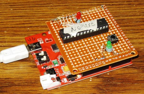
Well, this one looked a lot like most of the others I’d built. But it was from AdaFruit which has some of the best tutorials (accurate, complete, well documented) I’ve seen for the Arduino and it had different code. So I hacked up the hardware (See picture) using a RBBB Arduino and loaded the software. And guess what. It still didn’t work.
VERY FRUSTRATING!!
Well, I looked at the code and saw that it was set up to use the Serial Terminal. So I opened up the Serial Terminal and ran the program again.
This is the error message I got. (See picture)
After a lot of fooling around with Bootloaders I thought that this was not the correct signature that most software was looking for.
Signature: So what is a signature? Well, it turns out it is a specific code hard wired into the chip to identify it. Now all of the bootloader software seemed to be looking for 0x950F and not 9514 or 0x9514.
GeekSpeak: This is like ROM code that cannot be changed. By the way when you see programming code written starting with ‘0x’ that means it is a hexadecimal number. I won’t go into details but hexadecimal numbers go from 0 to 15 instead of 0 to 10.
Signature: So it turns out the bootloader software I’ve seen were based on the 0x950F signature which is the signature for the Atmega328P-PU chip. Being in electronics for 40 years, I usually ignored letters after the number. They are usually just revisions. This is basically true but in this case, the change also affects bootloading.
GeekSpeak: The PU refers to the packaging in this case PDIP which will fit into the 28 pin narrow IC socket preferred by most hobbyists.
Step 1: My Programmer
Solution: Well, I did get it to work with my breadboard setup with some software changes discussed later but I wanted a more permanent setup. I did have a protoshield like the one used in the AdaFruit writeup but I wanted to save mine for future projects so I decided to build my own shield.
Parts List:
PCB I used a hunk of the following:
5* Breadboard Bread Board Prototype 432 Points 5*7cm
$1.39 ebay
28 pin IC socket
$0.06 Taydaelectronics.com
2 1.2K resistors
1 red LED
1 green LED
1 pushbutton
Male header pins
About $0.25 Taydaelectronics.com
I had all of the above on hand but the total cost was about $1.
Step 2: Assembly
Problem: These PCBs have solder pads on only one side. I decided to put the pads on the bottom so the IC socket could be soldered in. The problem is the header pins going into Arduino go on the bottom couldn’t be easily soldered.
Solution: Well I decided to hot glue the headers to the PCB.
Problem: The standard prototype PCBs have 0.1” spacing between holes. This is standard for most electronics components. As many Arduino Geeks know, the original Arduinos had three connectors spaced correctly on 1/10 centers but the fourth connector was offset slightly. What this means is that Arduino shields cannot be easily made on standard prototype PCBs.
Solution: Hobbyists/Instructablers have come up with solutions for this. Most involve bending header pins to fit. Well, my header pins are a little short to bend so I decided to go a different route. For the one connector that was offset, I marked the location on the protoboard. Then I used a Dremel-clone to cut a slot there for the connector. I wonder if a laser engraver could cut this slot.
Hot-glue procedure: I wanted to use an Arduino (clone) to get the pins lined up and make the gluing easier. But I’m a messy hot gluer so I took some male header strip and inserted it part way into the female headers. (See picture)
Then I took a strip of transparent tape and pinched it in between the male and female header. (See picture). It’s hard to see the tape but the reflections are an indicator.
Then I folded the tape over onto the female headers. (See picture)
Then I did the same for the other side.
Next put the correctly sized male headers 2 eights and 2 sixs into the protoboard where you want them and push the headers onto the Arduino.
Next I hot-glued the header strips to the protoboard.
After it cools, you can carefully pull the headers out maybe with a knife or small screwdriver. The tape helps keep the glue from sticking to the female headers. Now it can be removed.
Next you can carefully hot glue the insides of the male header pins to the protoboard for strength.
For more detail: My Arduino In Circuit Programmer
- Why is the Atmega328P-PU preferred over the Atmega328-PU?
The Atmega328P-PU has a different device signature (0x950F) required by most bootloader software. - What error message indicates a signature mismatch?
The Serial Terminal displays an error when the bootloader looks for 0x950F but finds 0x9514. - How did the author solve the offset connector issue on standard PCBs?
The author used a Dremel-clone to cut a slot in the protoboard for the offset connector. - What method was used to align header pins before soldering?
The author inserted male headers into female headers and used transparent tape to hold them in place. - How can you prevent glue from sticking to female headers?
Placing a strip of transparent tape between male and female headers prevents glue adhesion. - What does the PU designation refer to in the chip name?
PU refers to the PDIP packaging which fits into a 28-pin narrow IC socket. - Why did previous attempts to program the chip fail?
Previous methods failed because the bootloader software looked for the wrong chip signature.