Summary of MQTT and Wifi Powered Mailbox Flag
Summary: The author built a battery-powered mailbox sensor using an ESP8266 (ESP-01) that wakes on lid movement, connects via WiFi, and publishes MQTT messages to a broker. Node-RED automates notifications (email or PushBullet). Design focuses on ultra-low deep-sleep current for year-long battery life, a simple plunger switch, and wiring/layout inside a 2xAA battery box. Firmware is flashed via USB-serial and supports OTA; Node-RED flow subscribes to the mailbox topic to send alerts.
Parts used in the Mailbox Sensor project:
- Battery box (3x AA, reused)
- 2 AA batteries
- ESP8266 module (ESP-01)
- Micro switch (momentary, spring removed)
- 47K resistor
- 4M7 resistor
- 100nF capacitor (replaced by 2.2uF in one ESP-01)
- 2.2uF capacitor (alternative to 100nF)
- Thin plastic tube (pen tube)
- Thick match stick or lollipop stick (plunger)
- Two strips of 4-pin female headers
- Wires for soldering
- USB Serial adapter (3.3V) for programming
- Hot glue / super glue (for mounting)
A couple of years I embarked on my own home automation project. It started off by building a server controlled 433 MHz transmitter build with an Arduino to switch lots of cheap PT2262 based remote switches. Later I added an Arduino based receiver for my weather station, hooked up the control contact of my EV charger, etcetera. Things grew more and more intertwined (and complicated!). So, a few months ago I decided to standardize everything based on MQTT for messaging, Node-RED for automation (both running on a single Raspberry Pi B+) and MariaDb for logging (running on my Synology NAS). Later I moved the MQTT broker (Mosquitto) and Node-RED over to the NAS too..
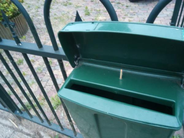
This instructable describes a silly for-fun project hooking my street mounted mailbox in this home infrastructure. The idea is that if somebody opens the fence mounted mailbox about 10 meters from the front door, it signals me on my phone and possibly other devices.
Step 1: Outline, Prerequisites and Parts
Outline
On a high level, the mailbox should, when opened, send a unique MQTT message to the broker, so that subscribers to that topic will be informed. Node-RED subscribes too and does some automation, in this case sending an email and/or a push message to my phone.
The mailbox should run on batteries and run for at least a year, and should do so using my WiFi network. As awakening a micro-controller and connecting to a WiFi network can take several seconds, I could not use the activation switch to cut the power. Instead, the processor should be allowed to finish it’s business after the lid of the mailbox has already closed.
Prerequistites
I assume your have modest soldering skills, have worked with the Arduino IDE a bit, and have installed the ESP8266 boards using the Boards Manager. You also need to have a 3.3 volt USB <> Serial adapter to program the micro-controller.
I also assume you have an MQTT broker and a Node-RED server running. If not, there are many instruction on the Internet, but I would advise to take the lazy route and use Peter Scargill‘s excellent install script if you want to run this on any Pi or Ubuntu, or use Andreas Spiess’s image for the Pi Zero W (links in the description of that video), which will save you a few hours of watching installation scripts running. Alternatively, you can make the firmware send out an email directly, but you will loose a lot of flexibility doing so.
Parts
- 1 closed, 3 AA battery box
- 2 AA batteries
- 1 ESP8266 module. For this project I used an ESP-01
- 1 micro-switch
- 1 47K resistor
- 1 4M7 resistor
- 1 2.2uF capacitor
- 1 thin plastic tube. I used a pen
- 1 thick, long match or lollipop stick. It should easily fit and move in the plastic tube
Step 2: Hardware: the Box, Switch and Wiring
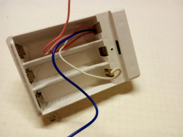
I started with an old battery box from a defunct Christmas decoration. It was designed for three AA sized batteries. As the ESP8266 will run nicely on 3 volt, I could use two batteries and use the third position for the micro-controller. Notice how the box had a small extra compartment that I could use for the activation switch. I used a very common type of switch shown in the pictures, but removed the spring that latches it in the on or off position. I soldered two thin wires to the NC contacts and glued it in the box with a tiny drop of super glue.
Next, I drilled a hole in the top cover matching a plastic tube taken from a ball pen. The hole lines up exactly with the switch and guides a plunger made from a thick match stick.
Finally, I soldered two more wires to the battery contacts and guided all four wires to the position of the third battery, where the micro-controller was going to be.
Step 3: Hardware: the ESP-01
Given the WiFi requirement, the entire project shouts ESP8266. This small WiFi controller has become the favorite workhorse of the tinkering community as a module that an be bought under EUR 2.50 and integrates a full WiFi and TCP/IP stack, with more than enough capacity to spare to run your own programs. The Arduino IDE (or Atom with the PlatformIO plugin) fully supports the ESP8266.
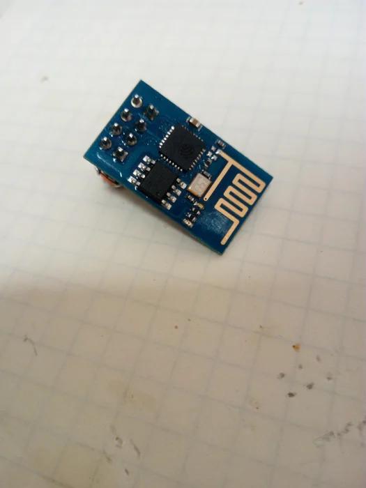
I would usually take an ESP-12F, but I had a tiny ESP-01 board laying around that was perfect for the job and fits nicely in the battery box. The only problem is that is is quite complicated to flash firmware in the ESP-01. More on that in the next step. There is one modification to make: You have to remove the red power LED from the board, as it continuously draws 3mA. With the LED removed, the module uses just a few tens of uA in deepsleep mode which will make it last for over a year on two quality AA batteries.
It turned out that I could use two strips of 4 pin female headers and solder on the few extra components in free form so that I could remove the ESP-01 to update the firmware, while it would still fit in the third battery compartment.
It is very important to correctly wire the ESP. Using the above cheat sheet, wire it up as follows.
- Battery plus to Vcc (D2), CH_PD (B2), RXD (D1), GPIO0 (C1), GPIO2 (B1) and a 47K resistor.
- Battery minus to GND (A1) and one wire of the switch.
- The other wire of the switch to a 100nF capacitor and a 4M7 resistor.
- The open ends of both resistors and the capacitor to RST (C2).
- TXD (A2) can remain unconnected.
Edit: I had to replace the ESP-01 because I made a silly mistake and destroyed it. Turned out that to my surprise the new ESP-01 did not reset with the original 100nF capacitor. It probably has a slightly different design. I replaced it with a 2.2 uF one and now it works again.
When done, everything can be mounted in the box, but hold on, first we need to program the module.
Step 4: Programming the ESP-01
To flash the firmware on your ESP-01, you can either build a small rig or buy an (almost) complete programmer for about 1 euro.
Programming hardware rig
Build a small rig with again two female headers for the ESP-01. Also, you need a USB <> Serial module, capable of providing 3.3 volt. Note that the ESP8266 chip is not 5 volt hardened, so a mistake here could kill your module. Anyway, again using the cheat sheet, wire your rig as follows:
- 3.3V from the USB<>Serial module to Vcc, CH_PD, RST and GPIO2.
- GND of the USB<>Serial module to GND and GPIO0.
- TXD of the USB<>Serial module to RXD.
- RDX of the USB<>Serial module to TXD.
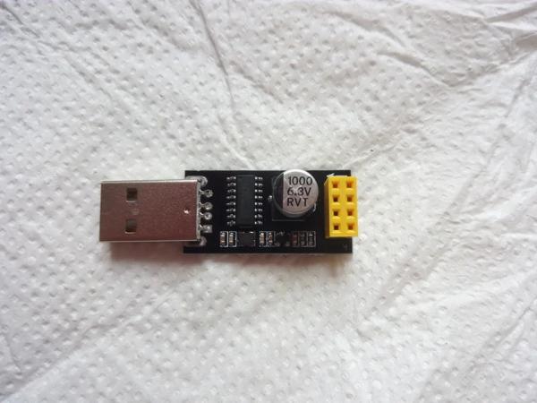
Pre-build programmer
Fun as it is to build your own stuff, the lazier approach is to get a ESP-01-to-serial interface from your favorite auction site, see the picture above. This is much easier, more compact and more reliable than a rig. However, some of these are not programmers, just serial interfaces. You need to solder a wire bridge between GND (pin A1) and GPIO0 (pin C1) on the backside of the interface, see the second picture. Note that the ESP-01 should be plugged in with the antenna facing the USB plug, not the other way around!
Note: they also exist with a switch, see third picture, very nice.
Load the firmware
Assuming an Arduino IDE of 1.8.3 or later, select Tools > Board and select the board you have. For an ESP-01 like I used, choose “Generic ESP8266 Module”, and set the following options (this should be all the defaults):
- Flash Mode: DIO
- Flash Frequency: 40MHz
- CPU Frequency: 80MHz
- Flash size: 512KB (64KB SPIFFS) Note: if you use a black ESP-01 board, choose 1MB (64KB SPIFFS)
- Debug port: Disabled
- Debug level: None
- Reset method: ck
- Upload speed 115200
- Port: select the port that is connected to your USB <> Serial interface. For my Ubuntu PC that was /dev/ttyUSB0
Hook up the rig / programmer, load the Sketch you can find here https://gitlab.com/jeroenmeijer/Mailbox.git. Supply your WiFi and MQTT broker credentials and your IP configuration in config.h and choose Upload.
Step 5: Assembling It All
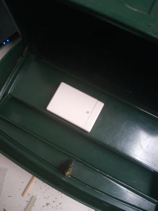
I drilled a hole for the plastic tube in the inner lid of my mailbox, as close to the hinge as possible, then hot-glued the battery box to the underside of that lid. Next I used a thick match as a plunger. I used a snip to cut the match to length so that the switch would open if the outer lid was closed. I checked connectivity by opening the lid while running mosquitto_sub to monitor MQTT messages (replace mqttbroker, user and password with your MQTT configuration):
$ mosquitto_sub -h mqttbroker -v -t "stat/#" -u user -P password
Approximately six second after the outer lid is opened the following MQTT message is published. The time is used to wake up the micro-controller and establish the WiFi and broker connection.
stat/mailbox/trigger {"vcc":3050, "flap":true, "prev":0, "RSSI":29, "version": "005"}
During this time, the micro-controller used approximately 70mA. When done, it goes into deep sleep and in my case it used less than 20uA. “flap” is always true, “vcc” states the battery voltage in mV and “prev” should be 0. If it is 1 or 2, it means the mailbox was unable to send a message earlier, either because it could not connect to the WiFi, or because it could not connect to the MQTT broker. “RSSI” is the strength of the WiFi signal. Both are very handy to diagnose problems.
It’s a good idea to monitor the battery voltage for a few days to ensure the device works as intended and doesn’t drain it’s battery for some reason.
The firmware is also able to update itself over the air (OTA), but that is a bit beyond the scope of this instructable. For those interested, the OTA configuration is also in config.h.
Step 6: Using Node-RED to Act on the MQTT Message
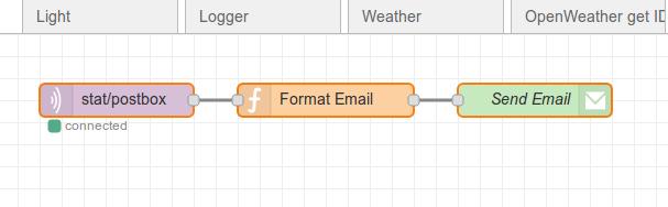
Finally, I created a simple flow in Node-RED. The first node subscribes to the topic of the mailbox (stat/postbox/trigger). When a message is received, the second node formats an email *). The final node sends it out to my gmail address, using gmail as SMTP server. My phone will then alert me of new mail.
I have added the Node-RED flow to a gitlab snippet so you can import it into your Node-RED flows.
Of course you can add some more nodes, for instance to log the mailbox events to MariaDb or SqlLite, or create extra alarms when the battery voltage goes below 2.7 volts.
Happy mail-hunting!
*) See next page, I am using PushBullet now instead of email.
Step 7: After-thoughts
There is always this feeling things could have been done better.
Switch
I would have preferred to use a (super) magnet and a reed contact instead of the somewhat clumsy plunger approach. There were two reasons. One is, there was no way I could make this work with the contact closing when the box was opened, and having it always closed meant a small current would always be flowing. In retrospect, the less than 1uA flowing through the 4M7 resistor would not have been a big deal in terms of battery life. The other was a more practical one. I made up this project on Saturday and wrote the software, build it all on Sunday from what was laying around. I simply didn’t have a reed contact in the junk box.
Note: as diy_bloke commented, reed contacts have a tendency to get sticky when magnetized for a long time, so maybe the plunger was not such a bad idea at all. We will see. *)
Message on emptying
The mailbox sends out a message when emptying it too. This is no big deal but with more people in the house getting the warning, one might end up in a loop checking the mailbox defying it’s entire purpose! There are a few ways around this, such as checking if the inner lid is lifted, and if so, do not send a message. Or instead of using the lid switch, install a detector at the bottom of the mailbox. Or a small reset button to be pressed when emptying it. However, all would complicate things and probably worsen reliability.
Messaging
Sending email is a rather effective but crude way of putting out the warning. A more elegant way would be a phone app, but I have not found an Android MQTT dashboard app that can be configured to trigger an operating system alert when a certain message is received. If there is one around, please add to the comments. **)
*) After more than a year in operation, it turns out the lollipop stick I used, basically hard rolled paper, has a tendency to shorten under the constant pressure of the switch spring. After some troubleshooting I replaced it with a wooden stick.
**) I am using PushBullet now for push messages, separate from the MQTT dashboard. A tiny Node-RED low interfaces to the API can be found here. Make sure you supply the access token in node “Prepare for pushbullet” and your email address for fallback purposes in node “Retry”.
Source: MQTT and Wifi Powered Mailbox Flag
- What microcontroller is used in the project?
The project uses an ESP8266 module, specifically an ESP-01. - Can the mailbox run on batteries for at least a year?
Yes; by removing the ESP-01 power LED and using deep sleep, the module can use a few tens of uA in deep sleep and last over a year on two AA batteries. - How does the mailbox notify me when opened?
The ESP-01 wakes, connects to WiFi, and publishes a unique MQTT message that Node-RED subscribes to and uses to send email or push notifications. - What wiring is required for the ESP-01 inside the battery box?
Battery plus to Vcc, CH_PD, RXD, GPIO0, GPIO2 with a 47K resistor; battery minus to GND and one switch wire; other switch wire to a capacitor and 4M7 resistor; resistor and capacitor ends to RST; TXD can remain unconnected. - How is the ESP-01 programmed?
Use a USB Serial adapter providing 3.3V or an ESP-01-to-serial interface, set Arduino IDE to Generic ESP8266 Module, configure board options, and upload the provided Sketch after filling config.h. - What MQTT message is published when the mailbox is opened?
A sample message is stat/mailbox/trigger {"vcc":3050, "flap":true, "prev":0, "RSSI":29, "version": "005"} published about six seconds after opening. - What do the fields vcc, flap, prev, and RSSI indicate?
vcc is battery voltage in mV, flap is true when triggered, prev indicates prior send failures (0 means none), and RSSI shows WiFi signal strength. - Does the firmware support OTA updates?
Yes, the firmware can update over the air and the OTA configuration is available in config.h, though OTA is beyond the scope of the instructable. - Can Node-RED be used to act on the MQTT message?
Yes; the author created a Node-RED flow that subscribes to the mailbox topic and formats and sends an email or PushBullet notification. - Are there suggestions to improve the switch mechanism?
The author considered a magnet and reed contact but used a plunger; reed contacts can stick when magnetized, so the plunger was acceptable.