Summary of Line Follower Robot – Arduino Mega/uno – Very Fast Using Port Manipulation
The article describes building a five-sensor line follower robot (Arduino Mega or Uno) that uses IR sensors to detect a black line and reacts (straight, slight/complete turns, U-turn, or stop). It emphasizes using direct port manipulation instead of digitalWrite/digitalRead for smaller, faster code. It details components, wiring for Mega and Uno (motor driver, motors, sensors to specific port pins), testing cases with serial monitor codes, and assembly suggestions including buying a kit and matching sensor types.
Parts used in the Line Follower Robot:
- 1 pcs L298N motor driver
- 1 pcs Arduino MEGA2560 or Arduino UNO
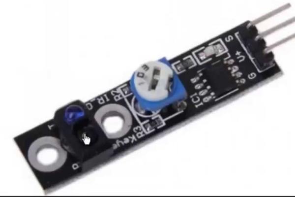
- 5 pcs line tracking IR sensor modules
- 4 pcs motors
- 4 pcs wheels
- Robot chassis
- Power supply
- Connecting wires
- Sensor shield (optional) or breadboard
- Glue gun (for fixing sensors)
- Optional: complete car kit (e.g., Elegoo EL-KIT-012)
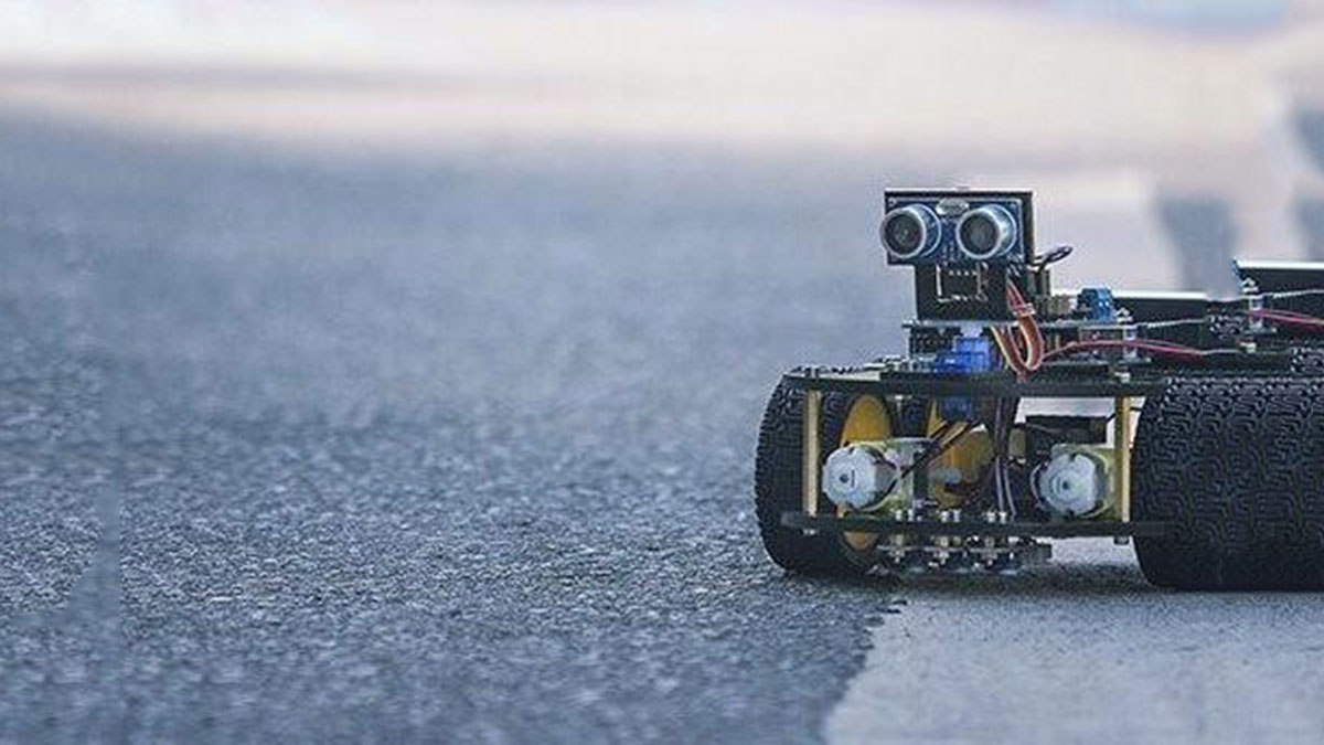
Line follower robot is a useful robot that is used in ware houses, industries, and stores etc, where it follows a dedicated path. The presented robot captures line position with IR Sensors. If the robot get off the line it will U turn and back to the line again. Also, it would stop while the designed spot is appeared.I used Direct port manipulation method (setting output pins directly) instead of using the Arduino default digitalWrite() functions. Using the port manipulation method in programming results in more space in HEX file and more speed while executingthe code.
For example:
Lets look at the blink example, this information is from the Arduino IDE
Sketch uses 928 bytes (2%) of program storage space. Maximum is 32,256 bytes.
Now using the following similar example (port manipulation )
<p>#include <br>#include

void setup()
{
DDRB = B11111111;
}
void loop()
{
PORTB = PORTB | 0x20; // Writes PORTB5 low
_delay_ms(500);
PORTB = PORTB & 0xDF; // Writes PORTB5 high
_delay_ms(500);
}</p>
the above Sketch uses 488 bytes (1%) of program storage space. Maximum is 32,256 bytes.
See the figure above ( compare between the two similar sketches).
see a great introduction on https://www.arduino.cc/en/Reference/PortManipulat…
read more about Direct port manipulation, using the digital ports [tutorial part 3]
More about Bitwise maths and logic operators [tutorial part 4].
Step 1: Components Required
List of Components:
- 1pcs L298N motor driver.
- 1pcs ARDUINO MEGA2560 Controller Board. Or ARDUINO UNO
- 5pcsline tracking module.
- 4pcs motor.
- 4pcs wheels.
- Power Supply.
- 1pcsRobot Chassis.
- Connecting Wires.
- Sensor Shield. (optional). or Bread Board.
Or you just a hole car kit.
Step 2: Purchasing and Assembling the Car Robot
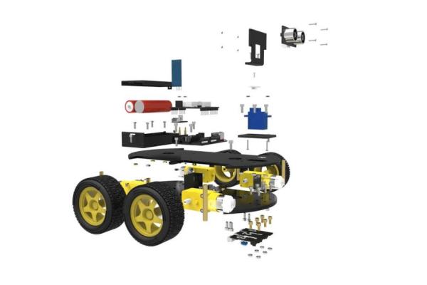
To make This Project doable for Every ages and make it easy as possible, I suggest to buy a hole kit from any supplier you like.
For example you can buy this Kit from Amazon Elegoo EL-KIT-012
you should buy extra IR sensors module from Amazon Infrared Black White Line Detection
you can see Instructions for Assembly
on ASSEMBLE ELEGOO SMART CAR ROBOT KIT V1.0
or on ASSEMBLE ELEGOO ARDUINO ROBOT VERSION 2.0
Remember: To buy extra IR sensors module If the kit comes with less than 5 IR sensor module.
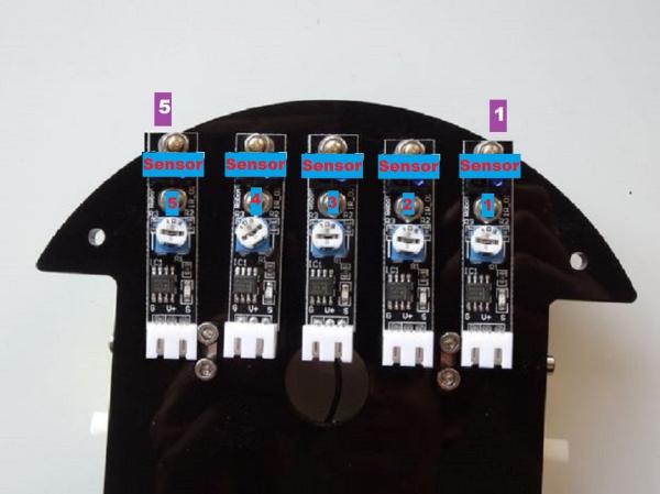
you should place the the additional IR sensor besides others and try to fix them at the same level so they look as figure above).
You can use a glue gun as tool to fix the additional sensors.
Note: All the five sensors must be identical because some give a different output signal while detecting the same color of lines. If you have already in hands a different type dont worry you just need to take the inverter of the output signal.
let say A = 1| then Y=~A= 0. as we clearly deal with Boolean values. Another solution is change all sensors output signals from high to low manually and vise versa.
Step 3: Getting Start: Study the Cases Testing It
The detailed procedures as follow:
- Give each Sensors a name depends on its potion on the car chassis:((see figure above )
- Ssensor number (1) = LF1
- Sensor number (2) = LF
- Sensor number (3) = MID
- Sensor number (4) = RT
- Sensor number (5) = RT1
- Connect The Five Sensors to the arduino mega or uno as follow: all Ground to Arduino Ground and Voltage inputs To the arduino +5V.
- LF1 Output Signals To pin A0.
- LF Output Signals To pin A1.
- MID Output Signal To Pin A2.
- RT Output Signals To pin A3.
- RT1Output Signals To pin A4.
- Use an electrical black tape to perform a straight lines on floor +a 90 degree turn.
- Download the attached Test Program. (Testing.ino)
- Connect the Arduino board to your computer and upload the sketch.
- Open Serial monitor and start placing the car on the line and wire down all possible condition.
Step 4: Test Results
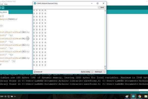
The serial monitor shows the results upon moving the line tracker sensor in a white background to a black line. The sensor module has a HIGH output when subjected to the black line and LOW output signal when subjected to others whit or light color. See Figures above
I Figure out all the situations that i need for my designed path.which is when:
- S1+ S2+S3 catch the line the car turn Fully left 90 degrees. Shows on Serial Monitor(11100).
- S3+S4+S5 catch the line the car turn Fully Right 90 degrees. Shows on Serial Monitor(00111).
- Olny S3 catch the line the car go straight. Shows on Serial Monitor(00100).
- All Sensors Catch the line line the car stop. Shows on Serial Monitor(11111).
- All Sensor out of the line the car make U Turn back to the line. Shows on Serial Monitor(00000).
These are the basic cases above.
- S1 catch the line the car turnslightly left. Shows on Serial Monitor(10000).
- S2 catch the line the car turnslightly left. Shows on Serial Monitor(01000).
- S4 catch the line the car go slightly right. Shows on Serial Monitor(00010).
- S5 Catch the line the car goslightly right.Shows on Serial Monitor(0001).
More possible case are found :
- S1+S2 catch the line the car turn slightly left.. Shows on Serial Monitor(11000).
- S2+S3 catch the line. the car Turn slightly left. Shows on serial Monitor(01100).
- S3+S4 catch the line. the care turn slightly right. Shows on serial Monitor(00110).
- S4+S5 catch the line the car turnslightly right.. Shows on Serial Monitor((00011).
Two more un necessary cases: ( I Would include just in case happens)
- S1+S2+S3+S4 catch the line. The car turn Fully left 90 degrees.(11110).
- S2+S3+S4+S5 catch the line. The car turn Fully right 90 degrees.(01111).
Obviously we have 15 cases that we need to teach the robot to handle.
Note: Microcontroller Boards can be programmed direct by Port. Making a hole port as an input port or an output port.
Each port has 8 bits can be used separately one at a time or just make all the port as an input or output and that what I am going to do next for programming.
See Also (How to control arduino pins from registers without digitalWrite and digitalRead)
Step 5: Connecting and Wiring !!! (Direct Port Register)
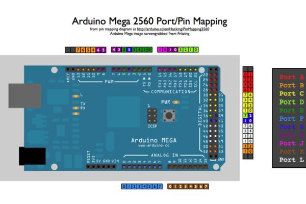
For Arduino Mega/uno see Port pin diagram above: for other board you may see the ports pin out and make change in connection only the sketch will work for sure, you just need to two different ports.
Note the two left motor Should Connect parallel to each other then to the motor drive as one. The same for the right motors.
- The Connection For Arduino Mega Left Motors First:
- The forward direction connect to pin 52 – PB2
- The back direction connect to pin 53 – PB0 // First bet at port B
- The right side motors
- The forward direction connect to pin 50 – PB3
- the back direction connect to pin 51- PB1
- The Sensors connection:
- S1 to pin 22 – PA0 // First bet at port A
- S2 to pin 23 – PA1
- S3 to pin 24 – PA2
- S4 to pin 25 – PA3
- S5 to pin 26 – PA4 // The fifth bet at port A
- The Connection For Arduino Uno Left Motors First:
- The forward direction connect to pin 10 – PB2
- The back direction connect to pin 8 – PB0 // First bet at port B
- The right side motors
- The forward direction connect to pin 11 – PB3
- the back direction connect to pin 9- PB1
- The Sensors connection.
- S1 to pin A0 – PC0 // First bet at port C
- S5 to pin A4- PC4 // The fifth bet at port C
- S4 to pin A3 – PC3
- S3 to pin A2 – PC2
- S2 to pin A1- PC1
Source: Line Follower Robot – Arduino Mega/uno – Very Fast Using Port Manipulation
- Can I use port manipulation instead of digitalWrite for this robot?
Yes. The article uses direct port manipulation to reduce program size and increase execution speed compared to digitalWrite. - What sensors are required and how many?
The project uses five identical IR line tracking sensor modules. - Which motor driver is used in the project?
The L298N motor driver is used. - How should sensors be connected to an Arduino Mega?
Connect sensor outputs to pins A0 through A4 (pins 22 to 26) with all grounds to Arduino ground and Vcc to +5V. - How should sensors be connected to an Arduino Uno?
Connect sensor outputs to A0–A4 mapped to port C pins PC0–PC4 (A0 to PC0, A1 to PC1, A2 to PC2, A3 to PC3, A4 to PC4) with common ground and +5V. - What are the main detected cases and robot behaviors?
Examples: middle sensor only (go straight), S1+S2+S3 or S2+S3+S4+S5 patterns cause full 90-degree turns, all sensors detect the line (stop), all off (U-turn back). - Do sensors output HIGH or LOW when over a black line?
The sensor module outputs HIGH when over a black line and LOW over white or light colors, as shown in the serial monitor tests. - What wiring is recommended for motors on Arduino Mega?
Left motors parallel to each other connected to PB2 (forward, pin 52) and PB0 (back, pin 53); right motors to PB3 (forward, pin 50) and PB1 (back, pin 51). - What wiring is recommended for motors on Arduino Uno?
Left motors to PB2 (forward, pin 10) and PB0 (back, pin 8); right motors to PB3 (forward, pin 11) and PB1 (back, pin 9). - Is it necessary that all five sensors be identical?
Yes. The article recommends using identical sensors because different sensors may give different outputs; otherwise invert the outputs to match.