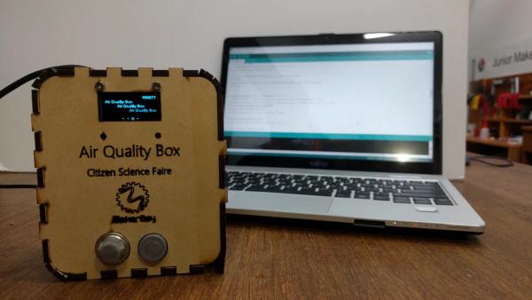
In this Instructable, I will walk you through the steps to build an IoT Air Quality Sensor. This is an inexpensive air quality sensor with reasonable accuracy and is accessible to internet through WiFi. This project is to integrate 3 sensors that detect different kinds of gases and particles with Nodemcu and then, send the data detected to the internet. The 3 sensors are MQ2 sensor for smoke, MQ9 sensor for carbon monoxide and PMS3003 G3 particle sensor for PM1.0, PM2.5 and PM10. Nodemcu 1.0 ESP8266 is a very good micocontroller for developing IoT project because it has an inbuilt WiFi function by ESP8266 chip. It provides easy and very stable connection to the internet.
Step 1: Bill of Materials
Things you would need:
- Nodemcu 1.0 ESP8266
- MQ2 gas sensor
- MQ9 gas sensor
- PMS3003 G3 particle sensor
- 3.3V to 5V boost converter
- 180ohm resistor x2 and 330 ohm resistor x2
- Analog Multiplexer 4051 (CD4051BE)
- 1.3 inches OLED monitor SSD1306
- 7.4V Li-ion battery
- Li-ion battery Charger Board
- Breadboard
Step 2: Nodemcu 1.0 ESP8266
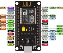
Nodemcu 1.0 ESP8266 is a very good micocontroller for developing IoT project because it has an inbuilt WiFi function by ESP8266 chip. It provides easy and very stable connection to the internet.
One drawback of Nodemcu is that it has only one analog I/O pin. For this project, there are 2 sensor, MQ2 and MQ9 gas sensor using analog output. In this case, a technique, called multiplexing, can be used. Instead of reading output from 2 sensor at the same time, reading data one by one. In this project, an analog multiplexer CD4051BE is used. It is a 8-channel multiplexer which means it can operate with 8 outputs. If you do not like to use multiplexer, simple circuit using diodes can also be achievable. You can take a look at Multiple Analog Inputs Using One Analoge Pin by Ingenerare or ESP8266 ADC – Multiple Analog Sensors by breagan22.
Another drawback is that Nodemcu only supplies 3.3V output. For many devices and the three sensors using in this project, they need 5V power supply to operate. Therefore, a 3.3V to 5V boost converter is needed to step up the voltage or simply supply the devices by other 5V supply.
There are many firmware for nodemcu. Nodemcu 1.0 is programmable by Arduino IDE, but few steps is needed before you can use it. You can look at Quick Start to Nodemcu (ESP8266) on Arduino IDE by Magesh Jayakumar.
Step 3: Connection
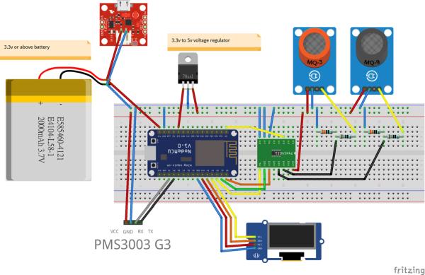
The above is the connection of all different components.
3.3V to 5V boost converter is connected to the 3.3V output of nodemcu.
I will explain how to connect other components below.
Step 4: Step 3: Connecting MQ2 and MQ9 Gas Sensor
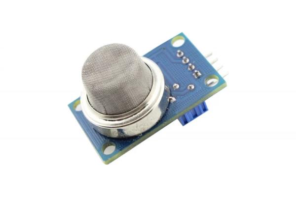
MQ2 and MQ9 gas sensor both have four pins:
- VCC
- GND
- DO (Digital Control)
- AO (Analog Output)
The analog output of MQ2 and MQ9 is between 0V to 5V whereas the analog pin of nodemcu can only read between 0V to 3.3V. That means nodemcu cannot read the data if MQ2 or MQ9 sensor output is above 3.3V. The data read is not accurate. Therefore, voltage is needed step down.
In this project, voltage divider by two resistors is used. The voltage output is determined by the ratio of the value of two resistors. I use 180ohm as R1 and 330ohm as R2 so that Vout is 3.3V.
So, Vin is connected to AO pin of MQ gas sensors. Vout is connected to channels of the multiplexer.
Only three pins of each sensor are used:
- Vcc to 5V supply
- GND to nodemcu GND pin
- Vout of voltage divider to CD4051BE channel 1 and channel 2(pin14 and 15)
Multiplexer connection:
- Vdd (pin 16) to 5V supply
- INH, Vee, Vss (pin 6, 7, 8) to nodemcu GND pin
- common out/in (pin 3) to nodemcu A0 pin
- A, B, C (pin 11, 10, 9) to nodemcu D0, D1, D2
A, B, C (pin11, 10, 9) are used to select channel for output.
A, B, C are digital input which means only read 0 and 1.
3-digit binary number is formed in the order of CBA.
As we use channel 1 and 2, denary number of 1 and 2 in 3-digit binary number are 001 and 010 respectively.
Therefore, when we want output of channel 1, D0 output 1, D1 and D2 output 0.
When we want output of channel 2, D0 output 0, D1 output 1 and D2 output 0.
Step 5: Connecting PMS3003 Sensor
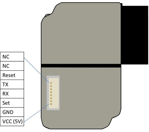
PMS3003 has 8 pins for different purposes. In fact, only 4 pins is used in this project:
- VCC (pin 1) to 5V supply
- GND (pin 2) to nodemcu GND pin
- RXD (pin 4) to nodemcu tx pin
- TXD (pin 5) to nodemcu rx pin
Step 6: Connecting 1.3 Inches OLED Display SSD1306
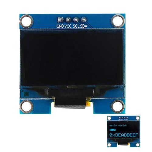
It has 4 four pins. Connection:
- VCC to 3.3V pin of nodemcu
- GND to GND pin of nodemcu
- SCL to D3 pin of nodemcu
- SCA to D4 pin of nodemcu
Step 7: Programming
I use Arduino IDE to program.
I use thingspeak as IoT platform.
Change to your API key in the program.
Change to your own SSID and password.
Source: IoT Air Quality Sensor