Summary of Intelligent Solar Garden Light using an Arduino- Part 1
Concise summary (under 100 words): The project upgrades a solar garden light by replacing low-capacity Ni‑MH AA cells with 1500mAh cells and adding a SparkFun Arduino Wee. The Arduino monitors the solar panel via analog input A0 and drives the LED control transistor via PWM on digital pin 3 (R1 removed). This enables soft on/off brightness fading and retains daylight shutoff logic. The original circuit uses two transistors, two resistors, a switch, and a diode to control three LEDs from a 3x AA Ni‑MH battery pack.
Parts used in the Intelligent Solar Garden Light:
- Solar panel
- 3x Ni‑MH AA batteries (original 600mAh)
- 3x Ni‑MH AA batteries (replacements, 1500mAh)
- Arduino Wee (SparkFun Electronics, 3.3V)
- Transistor Q1
- Transistor Q2
- Resistor R1
- Resistor R2
- Switch SW1
- Diode
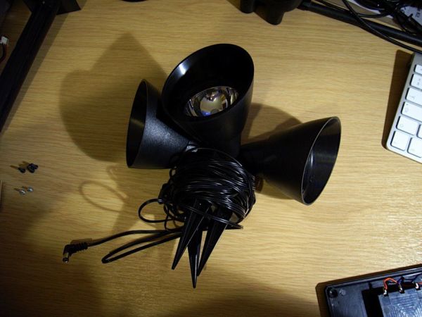
- 3x LEDs (spotlights)
- Battery compartment / power rails
I bought a solar powered garden light. The solar panel charges the batteries and when it gets dark the lights (3x LEDs) turn on until it either gets lights again or the batteries run out.
It has a small amount of intelligence (turns on when dark off when light) but not enough! Time for some upgrades. 😀
First, the batteries. The control box houses the batteries, which are three Ni-MH AA cells. They are 600mAh. (That’s not a typo – six hundred). I swapped them out for three 1500mAh Ni-MH cells that I don’t use anymore (because they are only 1500mAh).
Then I reverse engineered the circuit diagram for the electronics (nothing special there, two transistors, two resistors a switch and a diode).
I have a few ideas for sensors and transducers I want to add to the light, but I’ll start by adding a microcontroller. Step forward the Arduino Wee made by SparkFun Electronics.
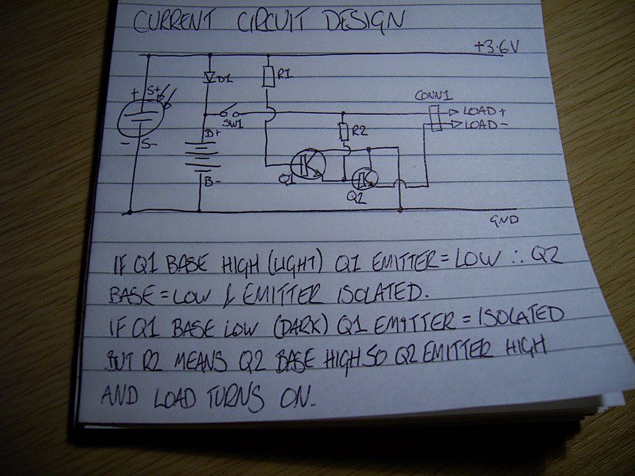
Step 1: Existing Circuit Diagram
When light is falling on the solar cell, transistor Q1 is turned on and connects the base of transistor Q2 to ground. This isolates the output of Q2 keeping the LED spotlights turned off. When it gets dark, Q1 is turned off, leaving the emitter isolated (floating). Assuming SW1 is turned on, the base of Q2 will be high due to R2. This will turn Q2 on and connect the emitter to ground. This completes the circuit for the LED spotlights and they turn on.
Step 2: Add the Arduino
So, the Arduino Wee is a 3.3V device (the normal Arduino is 5V TTL). The battery is made of 3x 1.2V cells giving 3.6V total. The Wee can cope with the extra 0.3V. I connected the Wee to the positive power rail after the switch and to the negative rail on the battery compartment. Then I unsoldered R1 and connected digital pin 3 to the base of transistor Q1, and the analogue input A0 to the positive rail of the solar panel. The Wee can now control the LED spotlights and knows if it’s light or dark.
Step 3: Soft on / off
As there’s intelligence in the solar garden light now, why just turn the lights on immediately when it gets dark? That’s not very sophisticated is it? Slowly turning the light on and getting brighter until it’s fully on, looks sooooo much better. 🙂
That’s why I used pin 3 – a PWM pin. 😉 You can see on the ‘scope the pulses. It’s showing about a 50:50 mark space ratio, so the light is at 50% brightness. It takes about two seconds to go from fully off to fully on. I think it looks cool.
LED’s
For more detail: Intelligent Solar Garden Light using an Arduino- Part 1
- What batteries did the project replace?
The project replaced three 600mAh Ni‑MH AA cells with three 1500mAh Ni‑MH AA cells. - Can the Arduino Wee run from the 3x AA Ni‑MH battery pack?
Yes, the Arduino Wee is a 3.3V device and copes with the 3.6V from three 1.2V Ni‑MH cells. - How does the Arduino detect light or dark?
The Arduino reads the positive rail of the solar panel on analog input A0 to determine light conditions. - How does the Arduino control the LEDs?
The Arduino drives the base of transistor Q1 from digital PWM pin 3 after R1 is removed, allowing it to control the LEDs. - Why was PWM used for the LEDs?
PWM on pin 3 enables soft on/off brightness fading so the lights gradually brighten over about two seconds. - Does the original circuit still provide daylight shutoff?
Yes, the original transistor-based daylight sensing remains and the Arduino interfaces to that logic via Q1. - What components made up the original electronics?
The original electronics consisted of two transistors, two resistors, a switch, and a diode controlling three LEDs. - Where is the Arduino powered from physically?
The Arduino is connected to the positive power rail after the switch and the negative battery rail.