Summary of How to Integrate a Temperature Sensor Circuit to an LCD
This project details building a temperature sensor circuit using an LM34 IC and an HD44780 LCD to display readings directly, bypassing computer interfaces. It requires an Arduino microcontroller to process data from the sensor and output it to the display. The guide provides specific wiring instructions for both components connected to an Arduino, emphasizing practical skills for creating real-world electronic products.
Parts used in the Temperature Sensor Circuit with LCD:
- LM34 Temperature Sensor IC
- HD44780 LCD
- Arduino
- 10KΩ potentiometer
- Jumper wires
In this project, we will go over how we can build a temperature sensor circuit and integrate it to an LCD so that we can get a readout of the temperature on the LCD.
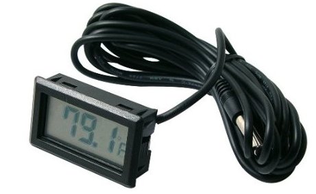
In previous projects with temperature sensor circuits, we built the circuit and then got a readout on the computer that we programmed the circuit with. In this project, we take it a step further. Instead of getting a readout on the computer, we will connect the circuit so that we can get a readout on an LCD display. This mimics a more real-life-like electronic product which you would see on the market.
To build this circuit, we will need 3 main components. We will need a temperature sensor IC. The one we will use in this project is a LM34 temperature sensor IC. We will need an LCD display. The type we will use is the popular HD44780 LCD. And we will need a microcontroller to get the readout from the sensor IC and then transfer the readout to the LCD>
To be successful building this circuit, you should know how to connect temperature sensor ICs and how to wire a HD44780 to an arduino.
To learn how to wire a LM34 temperature sensor IC to an arduino, see How to Build a LM34 Tempreature Sensor Circuit.
To learn how to wire an HD44780 LCD to an arduino, see How to Display Text on an HD44780 LCD with an Arduino.
Once you know how to connect these two devices, then interfacing them together is relatively easy and straightforward.
Knowing how to interface LCDs with other electronic devices is a valuable, valuable skill, because this is how most electronic consumer devices work in the industry.
Components Needed
- LM34 Temperature Sensor IC
- HD44780 LCD
- Arduino
- 10KΩ potentiometer
Of course you’ll need a whole bunch of jumper wires to wire all the connections.
But for this circuit, really, only these 4 main components are necessary.
Circuit Schematic
The circuit which we will build to interface a temperature sensor to an LCD for LCD readout is shown below.
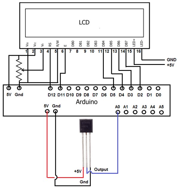
Connections of the HD44780 LCD to an Arduino
| LCD Pin | Function of LCD Pin | Arduino Pin |
| 1 | Gnd | Gnd |
| 2 | +5V | 5V |
| 3 | Contrast | NOT CONNECTED |
| 4 | RS (Register Select Pin) | 12 |
| 5 | R/W (Read/Write Pin) | Gnd |
| 6 | E (Clock Enable Pin) | 11 |
| 7 | D0 | NOT CONNECTED |
| 8 | D1 | NOT CONNECTED |
| 9 | D2 | NOT CONNECTED |
| 10 | D3 | NOT CONNECTED |
| 11 | D4 | 5 |
| 12 | D5 | 4 |
| 13 | D6 | 3 |
| 14 | D7 | 2 |
| 15 | Anode (for backlight) | 5V |
| 16 | Cathode (for backlight) | Gnd |
Connections of the LM34 to an Arduino
| LM34 Pin | Function of Pin | Connects to Arduino Pin… |
| 1 | +5V | +5V |
| 2 | Output | A0 |
| 3 | Gnd | Gnd |
For more detail: How to Integrate a Temperature Sensor Circuit to an LCD
- What is the main goal of this project?
To build a temperature sensor circuit that integrates with an LCD for a direct readout instead of using a computer. - Which temperature sensor IC is used in this project?
The project uses an LM34 temperature sensor IC. - What type of LCD display is required?
The popular HD44780 LCD is used for this circuit. - How does the LM34 Output pin connect to the Arduino?
The LM34 Output pin connects to Arduino Pin A0. - Which Arduino pin controls the RS function on the LCD?
Arduino Pin 12 is connected to the RS (Register Select Pin) of the LCD. - Can I use this circuit without connecting to a computer?
Yes, the circuit allows you to get a readout directly on the LCD display. - Why is interfacing LCDs considered a valuable skill?
It mimics how most electronic consumer devices work in the industry. - What is the function of the 10KΩ potentiometer in this setup?
The article lists it as a needed component, though the schematic notes the Contrast pin is not connected.