These frames are connected to the internet, which allows you to instantly send a kiss to a loved one. When my boyfriend and I were in a long distance relationship (for one and half years!), we communicated anyway that we could. We talked on the phone, sent presents and cards, fought through text and would leave our webcams on while sleeping so we knew the other was there if we needed them.
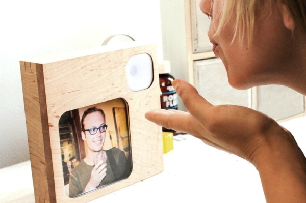
We communicated through what was convenient and what made sense, our phones and computers. Letters were written, but less frequently, they had that personal touch, but weren’t as immediate. Through all these ways, it still didn’t seem enough. I don’t think being able to stand next to one another and hold hands will ever be replaced with technology, but it’s nice to think of ways to make it more endearing and personalized. We now live together, but just recently I got a chance to make a project that touches upon this remote intimacy that we experienced while apart. This project translates a loving gesture, a blown kiss, into a message. This message is simply a talk bubble that lights up on the receiving end representing the digital kiss that has been sent. In the talk bubble is a red heart, but it can contain any image or whatever words you or your partner want it to.
This ‘ible will take you through the steps on how to make a pair of networked picture frames. It includes some wood working, circuit building and simple networking. Get connected with a loved one and send digital kisses from afar!
This project is dedicated to the one I love.
Step 1: Materials
First off – special thanks to JON-A-TRON for cutting and assembling the frames for me and helping this project come to be! He is a wood wizard.
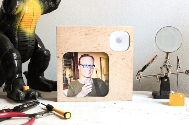
Both frames are 6 1/2″ x 6 1/2″ x 2″ with acrylic press fit details. The transparency sheet is for printing the heart on, this can be omitted for dry erase markers or another message or graphic you would like to put there.
Any Arduino supported microcontroller setup that has WiFi abilities can be used, for this project I used the Intel Edison.
Frames
[1] 8″ x 36″ hard maple, 1/2″ thick
[1] 9″ x 5″ clear acrylic, 1/8″ thick
[1] 18″ x 8″ white acrylic, 1/8″ thick
[1] 12” x 6” plywood, 3/8” thick
[1] 12” x 6” plywood, 1/8” thick
[16] size 4-40 screws, 3/8” long
[10] hex nuts for size 4-40 screws
[1] 1/4” long wood screw
[6] 1/2” standoffs for 4-40 screws
[1] 12” x 12” chip board, 32pt (1/32”) thick
[1] 5” x 10” piece of cardboard, 1/8” thick
[1] tube of 5-Minute Epoxy
[1] 4” x 4” mesh fabric
wood glue
Circuit
[1] Edison with Arduino dev board
[1] NPN transistor (2n2222)
[1] Electret Microphone Amplifier – MAX4466
[1] 1K resistor
[2] Adafruit Perma-Proto Quarter-sized PCBs or any small perf boards. There is a laser cut piece that is designed for the perma-proto, but you can work around it.
[2] 9 volt batteries
[2] 9 volt battery snaps
[2] 9 volt battery holders
[2] slide switches
[1] 16mm panel mount momentary button
hookup wire
Tools:
laser cutter
3D printer (optional if you find another way to make the wind funnel from step
wood router with 1/8″ rabbeting bit
clamps
mallet – preferably wooded or rubber
belt sander
palm sander
soldering iron
3D printer
Step 2: Laser Cut Wood
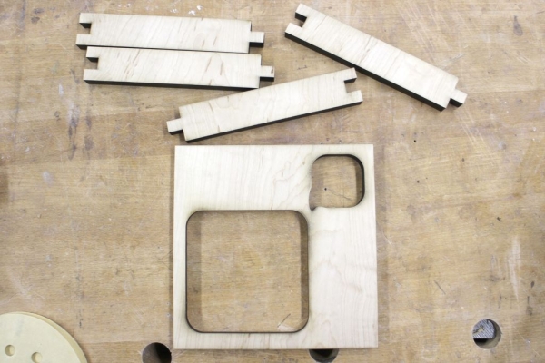
Download the attached files and open the FrameCut.ai file in Illustrator. Check that the stroke width is .001 pt and that the layout will fit within the piece of wood. To prevent scorch marks use application tape on the bottom and top of the wood. Scorch marks can also be removed with little sanding.
Depending on what kind of laser cutter you use, it could take a few passes to cut through 1/2” thick hard maple. If using a Metabeam laser cutter, one pass will be all you need. If using a 60 Watt Epilogue laser cutter, it will take a few passes. Protecting the wood is more important if using a laser cutter that calls for more passes.
The settings below, and to follow in the next steps, are for a 120 Watt Epilogue, if using a different cutter, do some research on what settings may be right for that machine.
Step 3: Laser Cut Acrylic
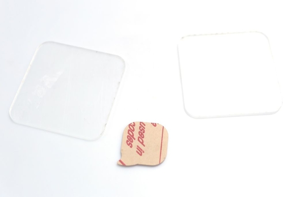
Keep all the protective films on the acrylic pieces after cutting.
Settings
Speed – 30%, Power – 50%, Frequency – 5000
From white:
1 x whiteTalkbbl
From clear:
2 x clearAcrylicWindow
Step 4: Laser Cut the Rest
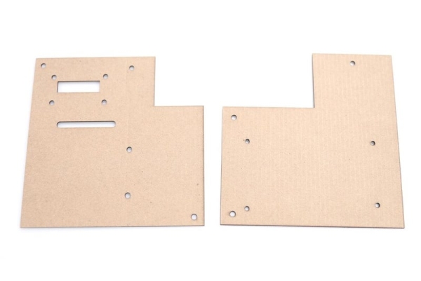
Chipboard
I needed to preserve my Edisons, so the designs for the receiving board is for a mini breakout that has male headers. The perf board gets screwed on to the board and the wires go through the cut out and connect via female headers. If you are soldering straight to your microcontroller, you may not need the extra long opening.
1 x rxMountBoard
1 x txMountBoard
Settings
Speed – 15, Power – 50, Frequency – 500
1/8″ Cardboard
2 x photoBacking
Settings
Speed – 30, Power – 18, Frequency – 500
1/8″ Plywood
1 x rxFrameBack
1 x txFrameBack
Settings
Speed – 8, Power – 100, Frequency – 500
Step 5: Route a Rabbet
A piece of clear acrylic is press fit in the front of each frame to provide protection for the displayed picture. To give room for the picture and it’s cardboard backing, we need to route a rabbet around the perimeter.
– Identify what will be the inside of each frame, this is the side that will be routed.
– Fit a 1/8″ rabbet router bit on your wood router and adjust the depth to 1/4″.
– Clamp the front down if using a hand router and route along the perimeter.
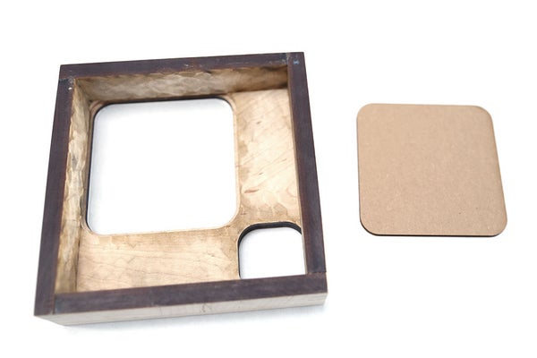
Step 6: Build Wooden Frames
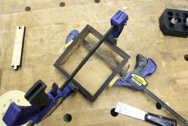
Glue and Clamp Sides
Grab the side pieces of the frames and apply some wood glue to the finger joints. Fit all four together and clamp to let dry. Though it may seem tricky, gluing all four at once is the easiest since you need the opposing sides to clamp against and keep the others in place.
Glue and Clamp Front
Apply wood glue to the front edge of each frame and fit the front on. To apply even pressure and protect the wood from markings, grab two pieces of scrap wood that are a little longer than the frames. Place them on top and place one clamp at each corner, making sure all edges are pressed together and making contact. Let dry completely.
Sand
Use a belt sander and palm sander to make even out the surfaces of the joints and to take off any scorch marks. There were a couple cracks in the wood where the clamps were applied too tightly, if this happens fill them in wood filler, let dry, then sand. If you would like to stain your frames, look for a stainable wood filler.
Step 7: Add Standoffs to Frames
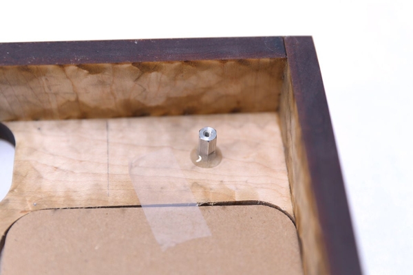
The frames consist of three layers, the outside wooden frame, mounting board and the frame back. Each layer will screw in to the next via standoffs, screws and hex nuts. In this step we will be adding hardware for the frame and mounting board to be connected. Before the frames can come together, the standoffs need to be added.
Take one of the mounting boards and mate it with it’s frame. Take a pencil and mark where the holes are on the inside of the frame.
Put the mounting board aside and grab three standoffs and the 5-Minute epoxy. Mix up about a teaspoon of the the epoxy and let it sit for one minute to let it firm up a teensy bit.
When ready, put the epoxy on the bottom of the standoff and around the perimeter. Carefully position it over the pencil marking.
I advise placing all three standoffs at once, putting the mounting board on top and checking the positions of the holes in the span of 5 minutes. This way you can make any adjustments to the standoffs that are needed before the epoxy sets.
Do this for the second frame, set aside to fully cure for about 15 minutes.
Step 8: 3D Print Wind Funnel
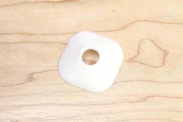
The purpose of the wind funnel is to direct the blown kiss to the mic. Download and print the windFunnel.stl file out of PLA or ABS, it doesn’t matter too much what material it’s made out of, it’s more about the shape. This could also be constructed out of wood, wood is just not my medium, so I went with 3D printing which was the quickest and most precise solution available to me. Feel free to construct this any way that works if you do not have access to a 3D printer.
Read more: InstaKISS : Networked Picture Frames