Introduction
Hello, tech enthusiasts! Welcome once again to Techatronic. We trust that you’re familiar with the concept of automation, which happens to be quite popular these days. In this piece, we’ll delve into the process of automating three LEDs utilizing a TSOP 1738 sensor module along with an Arduino UNO. Follow the circuit layout provided, then proceed to upload the corresponding code to the Arduino. Additionally, feel free to explore our articles covering topics such as IoT and fundamental electronics.
Description
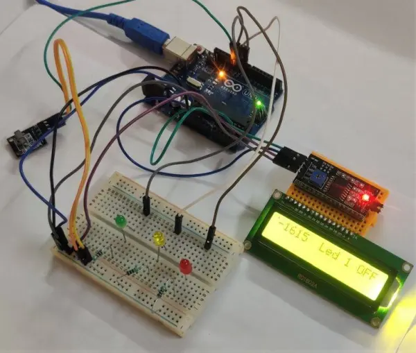
Upon powering the Arduino, the initial display on the LCD will showcase “remote control automation.” You have the flexibility to modify this text according to your preferences by altering the code.
Within this project, you gain the ability to remotely switch LED lights on or off simply by transmitting wireless signals. This functionality is made possible through the utilization of an IR sensor module (situated at the receiver) for signal decoding.
As the lights are toggled on or off, a message promptly appears on the LCD screen, reflecting the current state of the lights.
Additionally, you can explore the construction of a remote control robot using the TSOP 1738 module and Arduino, which is another facet of this project.
Although our current setup involves three LEDs, the system offers the flexibility to connect additional DC and AC appliances (employing relays) for expanded functionality.
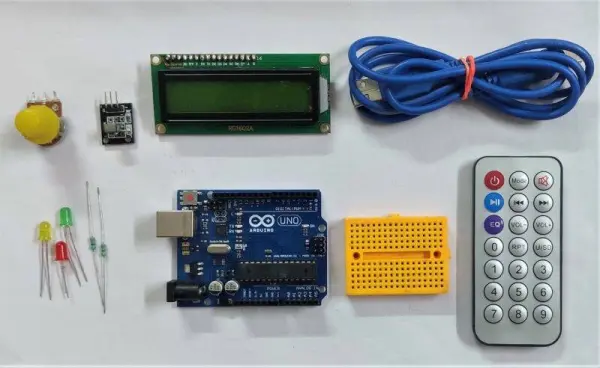
Components Required
Arduino UNO
TSOP 1738 sensor module
Three LEDs with varying colors
220 ohm resistors
10K potentiometer
Jumper wires and a breadboard
16×2 LCD display
USB cable required for code uploading
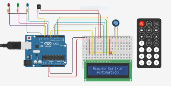
Circuit for Automation Using TSOP
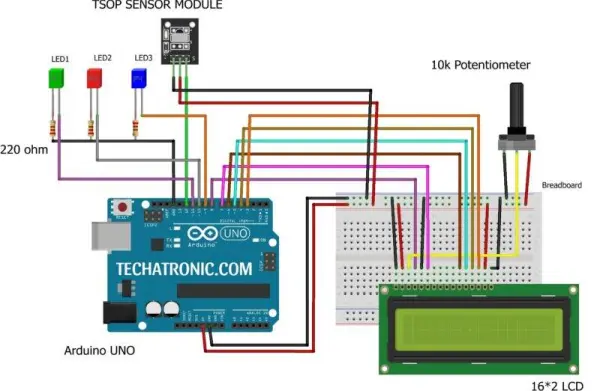
Utilize the TSOP 1738 sensor module by linking its VCC pin to the Arduino’s 5 volts pin. Access our article detailing the functionality of TSOP sensors with Arduino for further guidance.
Establish a connection by linking the GND pin of the TSOP sensor module to the Arduino’s GND pin. Subsequently, connect the OUT pin of the TSOP sensor module to the Arduino’s digital pin. Refer to the provided diagram for a visual representation.
For interfacing the 16×2 LCD, connect its pins to Arduino’s digital pins (3 to 8) as indicated in the diagram. To assist with these connections, consult our article illustrating the LCD-to-Arduino connections.
Proceed by connecting the positive leg of the first LED to an Arduino digital pin. Repeat this process for the positive legs of the second and third LEDs.
For all three LEDs, link their negative legs to the Arduino’s GND pin using a 220 ohm resistor.
Lastly, integrate a 10K potentiometer with the LCD module according to the schematic provided. Your circuit assembly is now complete.