Summary of How to Control Any Drone From Your Arduino Microcontroller Using Bluetooth
Summary: This project replaces a drone's receiver with an Arduino Uno that generates PPM signals, allowing control via an HC-05 Bluetooth module and a phone-based controller while retaining Betaflight features. It details configuring Betaflight for PPM, wiring power/ground/PPM, uploading and tuning Arduino PPM encoder code, assembling components, and testing. The author discusses tuning pulse/frame length and err trimming, mounting considerations, controller setup, flight results, and suggested improvements like lower-latency links and smaller microcontrollers.
Parts used in the How to Control Any Drone From Your Arduino Microcontroller Using Bluetooth:
- Arduino Uno
- HC-05 Bluetooth Module
- Drone with Flight Controller supporting PPM and Betaflight
- Drone battery
- PCB Board (preferably with vertical strips)
- 10k Potentiometer (optional)
- Micro-USB cable
- Male-Male and Female-Male wires
- Electrical tape
- Tools: soldering iron, solder wire, wire strippers, multimeter, precision screwdriver set
Hello Everyone!!!
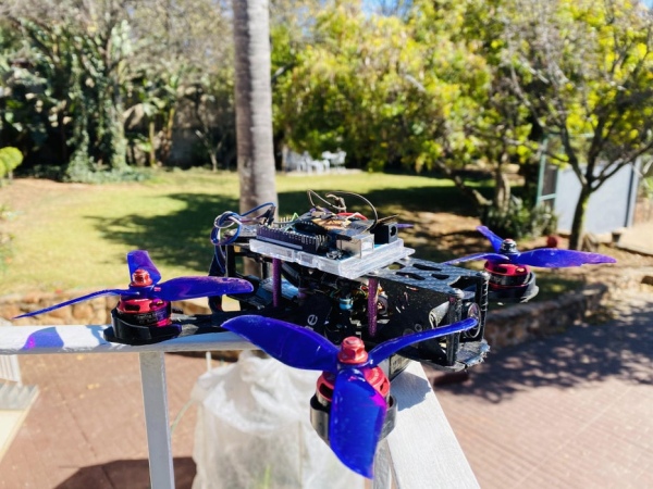
In this Instructable I am going to show you how I converted my (Commercial) RC drone that uses an RC radio system into a drone that is controlled by your Arduino using Bluetooth
Why would I want to control my drone from an Arduino?
I wanted to control my drone from an Arduino because I wanted to take a step into the automation of my drone. There was the option of building a drone and using the Arduino as the Flight Controller, but then I would miss out on all of the advanced features that the more popular firmware, like Betaflight, provides. This led to me thinking, “Why not replace the receiver of the drone with an Arduino, that way you still control the drone from your Arduino and you don’t have to compromise on its performance”. That was the idea, so let’s see how we did it.
Supplies
This is a list of all the main supplies needed for this project:
- Arduino Uno
- HC-05 Bluetooth Module
- A Drone – I built my own FPV drone. Make sure the Flight Controller supports the PPM protocol and it supports Betaflight.
- A drone battery
- PCB Board
- Arduino IDE
- Betaflight Configurator
- A phone that supports bluetooth.
- A Micro-USB for data transfer
- 10k Potentiometer (Optional but recommended)
This is a list of all of the tools needed for the project:
- A soldering iron
- Soldering wire
- Wire strippers
- Electrical Wires (Male – Male and Female – Male)
- Multimeter (One that has a continuity tester on it)
- Electrical Tape
- Precision Screwdriver Set
Step 1: The Theory and the Idea
The Theory
The theory behind this project is to use PPM signals which will be generated by the Arduino to control the drone. The Flight Controller usually receives PPM signals from the receiver which receives data from the transmitter. If we can generate the same PPM signals that the receiver sends to the Flight Controller with the data from the transmitter, we can encode our own data onto the PPM signals from the Arduino and control the drone from the Arduino. This means that a conventional transmitter and receiver is no longer required to pilot the drone and we can use any method of input to control the drone.
Well what are PPM signals?
A PPM signal (or Pulse Position Modulation) is used by most transmitters and receivers to transfer information from the transmitter to the receiver.
PPM is a single-wire signal that encodes many Pulse Width Modulated (PWM) signals. It’s commonly used in radio control of hobby aircraft and drones, where a radio transmits the PPM signal, which is decoded into many PWM signals to control RC servo motors.
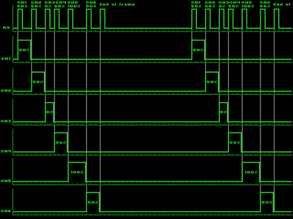
The signal that is sent is a series of pulses of fixed length, which are measured in microseconds . In electronics these pulses are an electrical signal of varying voltage (somewhere between +2.5V and +5V seems to be normal).Between these pulses are pauses of varying length (also measured in microseconds). In electronics these pulses are somewhere between 0V and +0.5V.
The data on this type of signal is encoded as the length of a pulse plus the length of the following pause. Or in other words: the time between the start of two pulses (or end, doesn’t matter since the pulse is of fixed length). This is also the reason it doesn’t matter whether the pulse is high or low; you simply pick either the rising or falling edge of a signal and measure the time between two rising or falling edges.
Channels follow each other in chronological order in the signal; i.e. channel 1 comes first, channel N last. The time between the pulses is used to generate a Servo Signal (in our case this signal will not control servos, but rather the motors on the drone). Pulses are usually around 500 microseconds in length (but as you will see in our case, the length might not always be 500 microseconds), the pauses are somewhere between 500 and 1500 microseconds. When you add those together and you get channel values of 1000 to 2000 microseconds, which happens to be the same range as used in Servo Signals.
After the last channel there’s an End Of Frame (or Beginning Of Frame) pause. This pause is somewhere between 5000 and 20000 microseconds in length; receivers don’t seem to be very strict with this. The pause may be of varying length, this way you can set a frame to a fixed length. Bear in mind that the longer the pause, the more latency you will experience, but the shorter the pause, the more unstable the communication will be between the Arduino and the Flight Controller. The best way to find the sweet spot is by trial and error.
The Idea
The main idea is to replace the receiver on the drone with an Arduino Uno. This will allow us to take control of the drone from any method of input that we desire, in this case Bluetooth, and to fully customize the drone to our liking.
Once the Arduino Uno is connected to the drone you will be able to embark on a vast plethora of projects and this is only one of them. This project highlights how precise the movements of the drone are when it is controlled by the Arduino and how easy it is to integrate different input methods onto the drone.
Let’s dive into the project.
Step 2: Configuring the Drone
The first step is to configure the drone so that it communicates using the PPM protocol. Most drones nowadays are, by default, configured to use the S-bus or I-bus protocols because it is a lot more efficient and reliable that PPM. But in order to allow communication between the Arduino and the drone, the PPM protocol is the best option.
- Connect the Flight Controller of your drone to your computer.
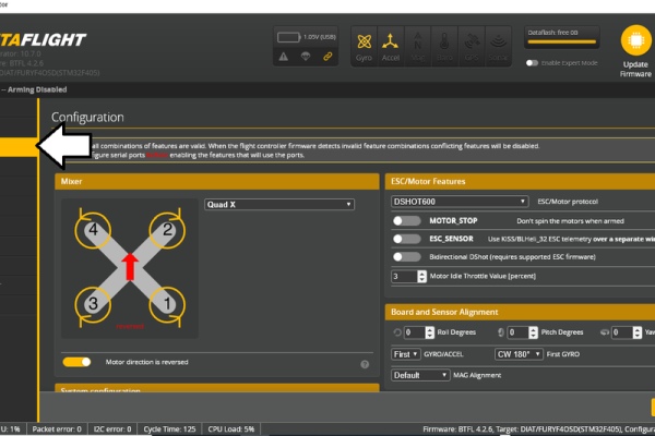
- Open Betaflight and locate the “Configuration tab”.
- Scroll down until you find the setting for “Receiver Mode”.
- Change the “Receiver mode” to “PPM RX input”.
- Click “Save and Reboot” which is at the bottom right of the screen.
Now that your drone has been configured let’s head on to the next step. Hopefully you haven’t had any challenges so far!
Step 3: Electronics and Soldering
For this step we will be making all of the electrical connections necessary for the project, so fire up your soldering iron and get your solder ready for some action. T
We first need to find which pins are the 5V, Ground and PPM on the Flight Controller. To find them you can use the Pinout Diagram from the manufacturers. There should be one available if you look up your specific Flight Controller on the internet and head over to the official website.
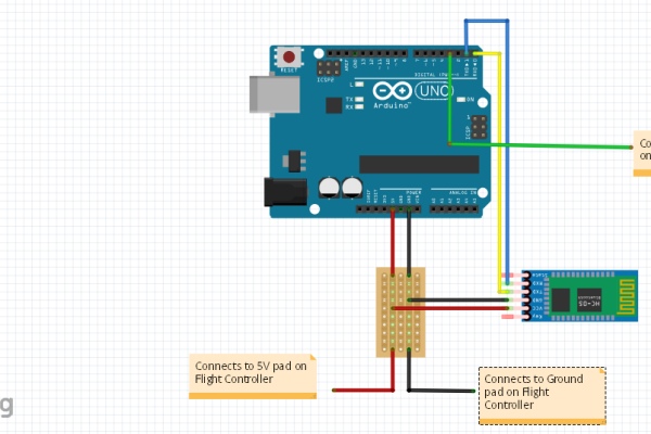
I have attached a Fritzing Image and some additional images to help with the connections:
- The first step that you should take is to make all of the connections to your HC-05 Bluetooth Module. For this I used Female-Male wires to connect it to the Arduino Uno and also to the PCB board. When connecting the Bluetooth Module to the Arduino, make sure that the TX pin of the Bluetooth Module is connected to the RX pin of the Arduino and the Rx pin of the Bluetooth Module is connected to the TX pin of the Arduino.
- Next you should get ready to connect all of the other components to the PCB. Preferably use a PCB with vertical strips because it will make all the connections easier and cleaner. Let me walk you through it:
- First connect the Ground rail and the 5V rail of the PCB onto the Ground pad and the 5V pad on the Flight controller. To find which pads to use on the Flight controller refer to its pinout diagram. The pads are usually located next to the PPM pad.
- Next connect the 5V and the Ground wires from the Bluetooth Module to the PCB board on their respective rails.
- The last step is to connect the 5V and the Ground pins from the Arduino board to the PCB board. This connection is used to provide power to the Arduino board, otherwise you would have to connect a 9V battery which is unnecessary if it can be powered directly from the drone battery.
- Connect pin 3 from the Arduino board to the PPM pad on the Flight Controller. This is the Signal wire which will send all of the commands to the drone.
And we’re done with all the connections, now test that nothing is incorrectly soldered by using the continuity tester on your multimeter. Once that’s done, head onto the next step.
Step 4: The Code
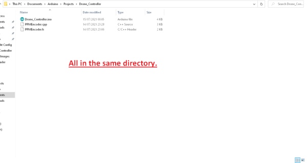
Here is the main code for the firmware. Download the files and make sure to save all 3 files in the same directory, on my computer I used the file path: “C:\Users\Administrator\Documents\Arduino\Projects\Drone_Controller”.
Once everything is saved correctly open “Drone_Controller.ino” in the Arduino IDE. If “PPMEncoder.cpp” or “PPMEncoder.h” are not already added to the file, click “Sketch” –> “Add File…” and add the necessary files.
Don’t upload it yet, there are some changes that may need to be made to allow the drone to fly smoothly.
I’ve made notes in the code but here are the main things to look out for:
- When you open “PPMEncoder.h” you will see that the only variables that might need changing are:
- PPM_DEFAULT_CHANNELS – This is the number of channels that you want to have on the drone.
- PPM_PULSE_LENGTH_uS – This is the length of the pulse, you might have to play around with the variable find the correct value. The most common values are either 0.5 or 0.3
- PPM_FRAME_LENGTH_uS – This is the length of the separation pause. The larger the value, the more stable the readings are and the higher the latency, but the lower the value, the less stable the readings are and you’ll have a lower latency. Try to play around with this value until you find your sweet spot. In the next step are the instructions on an easy method to find the sweet spot value
/* This is the header file, the only things that might need to be changed are:
 * PPM_DEFAULT_CHANNELS - This is the number of channels that you want to have on the drone
 * PPM_PULSE_LENGTH_uS - This is the length of the pulse, you might have to play around with the variable find the correct value
 * PPM_FRAME_LENGTH_uS - This is the length of the separation pause. The larger the value, the more stable the readings and the higher the latency, but
 *                       the lower the value, the less stable the readings and a lower latency. Try play around with this value until you find your sweet spot.
 */
#ifndef _PPMEncoder_h_
#define _PPMEncoder_h_

#if defined(ARDUINO) && ARDUINO >= 100
#include "Arduino.h"
#else
#include "WProgram.h"
#endif

#define PPM_DEFAULT_CHANNELS 8

#define PPM_PULSE_LENGTH_uS 25
#define PPM_FRAME_LENGTH_uS 40000

class PPMEncoder {

  private:
    int16_t channels[10];
    int16_t err;
    uint16_t elapsedUs;

    uint8_t numChannels;
    uint8_t currentChannel;
    byte outputPin;
    boolean state;

    uint8_t onState;
    uint8_t offState;


  public:
    static const uint16_t MIN = 1000;
    static const uint16_t MAX = 2000;

    void setChannel(uint8_t channel, uint16_t value);
    void setChannelPercent(uint8_t channel, uint8_t percent);

    void begin(uint8_t pin);
    void begin(uint8_t pin, uint8_t ch);
    void begin(uint8_t pin, uint8_t ch, boolean inverted);

    void interrupt();
};

extern PPMEncoder ppmEncoder;

#endif
- When you open “PPMEncoder.cpp” you may only need to change this value:
- err – This value will help you trim the fluctuating readings that you may get on Betaflight even when you are not transmitting any values. 8 worked extremely well for me.
/* This is the main code of the program. The only value that might need to be changed is:
 *  err - This value will help you trim the fluctuating readings that you may get on Betaflight even when you are not transmitting any values. 8 worked extremely well for me
 */
#include "PPMEncoder.h"

PPMEncoder ppmEncoder;

void PPMEncoder::begin(uint8_t pin) {
  begin(pin, PPM_DEFAULT_CHANNELS, false);
}

void PPMEncoder::begin(uint8_t pin, uint8_t ch) {
  begin(pin, ch, false);
}

void PPMEncoder::begin(uint8_t pin, uint8_t ch, boolean inverted) {
  cli();

  // Store on/off-State in variable to avoid another if in timing-critical interrupt
  onState = (inverted) ? HIGH : LOW;
  offState = (inverted) ? LOW : HIGH;

  pinMode(pin, OUTPUT);
  digitalWrite(pin, offState);

  err = 8;
  state = true;
  elapsedUs = 0;
  currentChannel = 0;

  numChannels = ch;
  outputPin = pin;

  for (uint8_t ch = 0; ch < numChannels; ch++) {
    setChannelPercent(ch, 0);
  }

  TCCR1A = 0;

  OCR1A = 100;
  TCCR1B = (1 << WGM12) | (1 << CS11);
  TIMSK1 = (1 << OCIE1A); // enable timer compare interrupt

  sei();
}

void PPMEncoder::setChannel(uint8_t channel, uint16_t value) {
  channels[channel] = constrain(value, PPMEncoder::MIN, PPMEncoder::MAX);
}

void PPMEncoder::setChannelPercent(uint8_t channel, uint8_t percent) {
  percent = constrain(percent, 0, 100);
  setChannel(channel, map(percent, 0, 100, PPMEncoder::MIN, PPMEncoder::MAX));
}

void PPMEncoder::interrupt() {
  TCNT1 = 0;

  if (state) {
    digitalWrite(outputPin, onState);
    OCR1A = PPM_PULSE_LENGTH_uS * 2;

  } else {
    digitalWrite(outputPin, offState);

    if (currentChannel >= numChannels) {
      currentChannel = 0;
      elapsedUs = elapsedUs + PPM_PULSE_LENGTH_uS;
      OCR1A = (PPM_FRAME_LENGTH_uS - elapsedUs) * 2 - err;
      elapsedUs = 0;
    } else {
      OCR1A = (channels[currentChannel] - PPM_PULSE_LENGTH_uS) * 2 - err;
      elapsedUs = elapsedUs + channels[currentChannel];

      currentChannel++;
    }
  }

  state = !state;
}

ISR(TIMER1_COMPA_vect) {
  ppmEncoder.interrupt();
}
In the main code of, “Drone_Controller.ino”: everything has been documented in to code and is easy to follow.
//Developed by Iloke Alusala
#include "PPMEncoder.h"

//Choose either pin 2 or pin 3 because they are interrupt pins. On other boards you can use any pin that has an interrupt
#define OUTPUT_PIN 3

// This value will store the input from the Bluetooth Controller
char state = '0';

// These variables represent the values of each channel, from 1 - 8. You can change how many variables you have depending on the number of channels you have.
int v1 = 50,v2 = 50,v3 = 0,v4 = 50,v5 = 0, v6= 0, v7 = 0, v8 = 0;

//These are the values used to increment or decrement each channel's percent when they are triggered by your input.
int inc1 = 2, inc2 = 2, inc3 = 2, inc4 = 2;

//const int potPin = A3;

void setup() {
  //Begin serial communication.
  Serial.begin(9600);

  //Configure and initiate the encoder. The encoder will send the PPM Signals to the drone.
  ppmEncoder.begin(OUTPUT_PIN);

  //Set default values so that the drone start abruptly.
  //This is how to set values of each channel: ppmEncoder.setChannelPercent(channel, percent). The channels are 0-indexed (so they start at 0) and the percent is from 1-100.
  ppmEncoder.setChannelPercent(0, 50);
  ppmEncoder.setChannelPercent(1, 50);
  ppmEncoder.setChannelPercent(3, 50);

  //pinMode(potPin, INPUT);
}

void loop() {

  if(Serial.available() > 0){
    // State stores the values that are sent by the bluetooth controller, based on which value is sent, the drone will respond accordingly
    state = Serial.read();
    // The possible values of state that are used in the case statement can be represented by any character, so feel free to change them to anything.
     switch(state){
      //This controls the throttle value, +inc3 (+2%).
      case 'U': v3 += inc3; v3 = min(v3, 100); ppmEncoder.setChannelPercent(2, v3); break;

      //This controls the throttle value, -inc3 (-2%).
      case 'D': v3 -= inc3; v3 = max(v3, 0); ppmEncoder.setChannelPercent(2, v3); break;

      //This controls the yaw value, -inc4 (-2%). The rate at which drone will turn left.
      case 'T': (v4 > 50) ? v4 = 50 + inc4: v4 = v4;v4 -= inc4; v4 = max(v4, 0); ppmEncoder.setChannelPercent(3, v4);break;

      //This controls the yaw value, +inc4 (+2%). The rate at which the drone will roll right.
      case 'X': (v4 < 50) ? v4 = 50 - inc4: v4 = v4;v4 += inc4; v4 = min(v4, 100); ppmEncoder.setChannelPercent(3, v4);break;

      //This controls the pitch, +inc2 (+2%) The rate at which the drone will pitch downwards.
      case 'F': (v2 < 50) ? v2 = 50 - inc2: v2 = v2;v2 += inc2; v2 = min(v2, 100); ppmEncoder.setChannelPercent(1, v2);break;

      //This controls the pitch, -inc2 (-2%). The rate at which the drone will pitch upwards.
      case 'B': (v2 > 50) ? v2 = 50 + inc2: v2 = v2;v2 -= inc2; v2 = max(v2, 0); ppmEncoder.setChannelPercent(1, v2);break;

      //This controls the roll, -inc1 (-2%). The rate at which the drone will roll left.
      case 'L': (v1 > 50) ? v1 = 50 + inc1: v1 = v1;v1 -= inc1; v1 = max(v1, 0); ppmEncoder.setChannelPercent(0, v1);break;

      //This controls the roll, +inc1 (+2%). The rate at which the drone will roll right.
      case 'R': (v1 < 50) ? v1 = 50 - inc1: v1 = v1;v1 += inc1; v1 = min(v1, 100); ppmEncoder.setChannelPercent(0, v1);break;

      //This controls Aux1
      case '1': if(v5 == 100){
        v5 = 0;
        ppmEncoder.setChannelPercent(4, v5);
      }
      else{
        v5 = 100;
        v1 = 50, v2 = 50, v3 = 0, v4 = 50;
        ppmEncoder.setChannelPercent(0, v1);
        ppmEncoder.setChannelPercent(1, v2);
        ppmEncoder.setChannelPercent(2, v3);
        ppmEncoder.setChannelPercent(3, v4);
        ppmEncoder.setChannelPercent(4, v5);
      }
      break;

      //This controls Aux2
      case '2': (v6 == 100) ? v6 = 0 : v6 = 100; ppmEncoder.setChannelPercent(5, v6);break;

      //This controls Aux3
      case '3': (v7 == 50) ? v7 = 0 : v7 = 50; ppmEncoder.setChannelPercent(6, v7); break;

      //This controls Aux4
      case '4': (v8 == 100) ? v8 = 0 : v8 = 100; ppmEncoder.setChannelPercent(7, v8); break;
     }

      /*
       int potValue = analogRead(potPin);
       int val = map(val, 0, 1023, 0, 500);
       #define PPM_PULSE_LENGTH_uS = val;
      */
     //Print the input, this is to check that everything is functioning correctly
     //Serial.println(state);
}
}
Attachments
Step 5: Tuning the Drone

Now you can upload the code and open up Betaflight
With Betaflight open go to the “Receiver” tab and this is where you can monitor the stability of the signal and whether the channel readings are incorrect and need trimming.
Here is a tip that in order to find the “sweet spot” values quickly:
After sleepless nights of trying to find suitable values from a very wide range, I decided that it would be a lot more efficient if I used a potentiometer and “scrolled” through the range until I found the “Sweet spot” values.
This came in handy especially when I was looking for a suitable Pulse Length because my Flight Controller would not work with the conventional 0.5ms or 0.3ms, my Flight Controller actually only worked with values in the range 0.01ms – 0.05ms! So this method definitely helped when looking for the Pulse Length.
I repeated the step above when looking for the err value. When you upload the code to the Arduino board and it starts sending the PPM signals to the Flight controller, you can monitor the values in Betaflight, you might notice a lot of fluctuations in the readings and this makes the drone unflyable. To fix this I added the err variable in the code. When you increase this value it trims all the readings in Betaflight downwards and when you increase this value, it trims all the readings in Betaflight upwards. Once you have trimmed all the values so that channels 1, 2 and 4 are reading 1500 and channel 3 is reading 1000 you will be ready to fly.
If you want to use the potentiometer to help get the right values, I have attached a Tinkercad Image to help with the connections. The lines of code used when the potentiometer has been connected have been commented out of the code but the specific lines are as follow:
const int potPin = A3;

void setup() {
  pinMode(potPin, INPUT);
}

void loop() {
  int potValue = analogRead(potPin);
  int val = map(val, 0, 1023, 0, 500);
  #define PPM_PULSE_LENGTH_uS = val; //Change which variable you want to test
The first thing that you might notice if you have not adjusted the values so that they accommodate your Flight Controller is that you might not pick up any readings in Betaflight at all! This is probably due to you not having the right value for “PPM_PULSE_LENGTH_uS”.
The second thing you might notice is that the values are very jumpy and unstable. This is due to the value “PPM_FRAME_LENGTH_uS” being too low. Increase this value until the values are stable.
Once both of the above mentioned issues have been dealt with, the last variable to tune is “err”. If you notice that the values of each channel are not at the correct default positions and they are not fluctuating, you need to adjust the “err” variable accordingly. As I mentioned above when you increase this value it trims all the readings in Betaflight downwards and when you increase this value, it trims all the readings in Betaflight upwards. The first Screenshot of Betaflight that I have attached shows how unstable the channel readings were before I trimmed them using the err variable in the code. The second screenshot shows the channel values after I trimmed them. It makes a big difference!
Once you are receiving stable values you can move onto the next step.
Step 6: Assembly
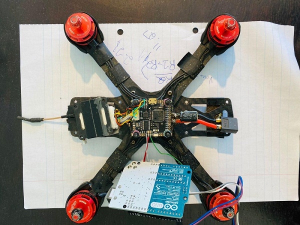
Due to the size of the Arduino Uno, there is not a lot of space on the interior of the drone which led to me having to place the Arduino board on the outside of the drone. I usually keep the battery on top but I decided to move it to the bottom of the drone and to place the Arduino board on the top of the drone.
I secured the Arduino Uno to the top of the drone with some electrical tape. I kept the wires very short to prevent them from hitting the propellers mid flight and I placed the Bluetooth module at the back of the drone under the battery cable. As for the PCB, because it was so small and the connections were exposed, I used some electrical tape to cover it and secure it to the Arduino.
Here is the order that I followed in each image:
- Image 1: All the connections have been made and everything is exposed.
- Image 2: I have reattached the camera of the drone onto the frame and connected it to the Flight Controller. I have also placed the VTX back on top of the Flight Controller.
- Image 3: I have reattached the top part of the frame onto the drone.
- Image 4: I have flipped the drone over and attached the screws to connect the bottom part of the frame to the top part of the frame.
- Image 5: I have flipped the drone over and attached the Arduino board to the top of the drone using electrical tape
- Image 6: I have placed electrical tape on the PCB and secured it onto the Arduino board.
- Image 7: In this image you can see where I placed the Bluetooth Module. I put it between the frame and the battery wires.
- Image 8: This image shows the complete drone with everything attached, but without the propellers on.
- Image 9: This is the entire drone with everything on and it is ready to fly!
There is a lot of freedom when it comes to assembly because not all drone frames are designed the same, so the placing of the components on my drone my not work on yours. So make sure to play around with it and get creative!
Step 7: The Controller
We can’t fly the drone without a controller so let’s get this sorted out.
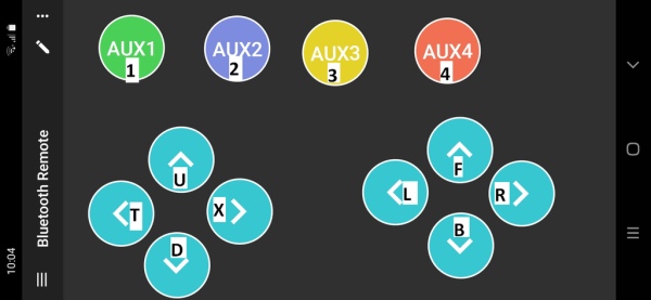
I looked all around the Google Play Store for some Arduino related Bluetooth controllers but very few were customizable controllers. Eventually I settled on this Bluetooth Controller purely because it is customizable and I thought it would be an interesting way to control the drone compared to the conventional joystick controls. Using this controller also allows you to have more precise control over the drone.
I have attached an image that will help you configure your layout and I have overlaid the values that each button will send to the Arduino. Setting up the controller is very easy and if you get stuck you can follow this “Tutorial”.
Note: The overlaid values are the values that you need to set when you create the buttons. Enter those values in the “On Press Down” prompt.
To set the function of each Aux button, you will have to do that in Betaflight. My personal preference when flying the drone is to use self-leveling, which I set up as Aux 3, because it makes the flight a lot smoother and it helps keep the drone stable during take-off and landing.
Now for the part that we have all been waiting for.
Once you’ve set up your Bluetooth controller, power on the drone and connect your phone to the Bluetooth Module on the drone. This is the last step, arm the drone and get ready to fly!
Step 8: Flight Review
In the video above I am controlling the drone from my phone using the Bluetooth controller. The movements of the drone are quite precise and the flight characteristics are similar to those when it is controlled by an regular RC system. I am very pleased with the outcome of the project!
Step 9: Improvements, Safety and Overall Thoughts

Improvements:
- In terms of how the Arduino sent signals to the drone I found it quite stable and reliable, but I know that the code can be written more efficiently in order to reduce the latency with each transmission.
- I think that I will definitely change the method of transmission from Bluetooth to a medium that has a lower latency because there is a noticeable delay between when you press the button on the controller and when the drone responds. This is more an issue of safety because in times where you need an instant response you might be just a fraction of a second to late. I would also change the method of transmission because although Bluetooth was the easiest to configure, it has a very limited range which can cause problems if you want to fly it long range.
- I am currently working on a system that you can use to add to the drone in order to measure the voltage of the battery safely and send it back to the controller. At the moment it is best to use timer and to measure the voltage of the battery when you land. This is to avoid the voltage of the battery from dropping to a dangerously low voltage which could lead to damage of the battery.
- It would also be ideal to get a smaller microcontroller such as an Arduino Nano which could possibly fit on the interior of the drone frame.
Safety
At the end of the project the main concern is the safety of the drone and those using it. It may seem like a “toy” but there are a lot of things that could go wrong.
Some of the safety measure that can be kept in place when flying the drone are:
- Fly it in an environment where there are very few obstructions and few people.
- Fly the drone at a distance from any object, including yourself so that you have adequate time to respond if the drone malfunctions.
- Store the battery safely, there are guidelines that you can follow from the drone battery manufacturer in order to use and store the drone battery safely.
- Don’t fly the drone too far away from the controller because a loss of signal from the controller can pose a risk to anything around or in the path of the drone
- The most important safety rule is to apply common sense and to not fly it in any risky manner.
Conclusion:
At the end of the project I was quite satisfied at how well the Arduino was able to send the PPM Signals to the drone. I can definitely see myself doing more projects related to automation with the Arduino and the drone. As for the flying, I felt that it was extremely stable and satisfactory. Due to the nature of how powerful the drone was and how accurate the readings were from the Arduino ,I felt like it was a perfect combination.
I hope you enjoyed and followed this Instructable and you are as excited about this project as I am.
Source: How to Control Any Drone From Your Arduino Microcontroller Using Bluetooth
- What is the main idea of this project?
Replace the drone receiver with an Arduino Uno that generates PPM signals so the drone can be controlled via Bluetooth while keeping Betaflight features. - What protocol must the Flight Controller support?
The Flight Controller must support the PPM protocol and Betaflight. - How do you configure the drone to use PPM?
Connect the Flight Controller to the computer, open Betaflight, set Receiver Mode to PPM RX input, then Save and Reboot. - Which Arduino pin is used to send PPM to the Flight Controller?
Pin 3 (an interrupt-capable pin) is used as the PPM signal output to the Flight Controller. - How should the HC-05 Bluetooth module be wired to the Arduino?
Connect HC-05 TX to Arduino RX, HC-05 RX to Arduino TX, and connect their 5V and Ground to the PCB/flight controller power rails. - Which code files are required for the project?
Drone_Controller.ino, PPMEncoder.cpp, and PPMEncoder.h saved in the same Arduino project directory. - What variables commonly need tuning in PPMEncoder.h?
PPM_DEFAULT_CHANNELS, PPM_PULSE_LENGTH_uS, and PPM_FRAME_LENGTH_uS often need adjustment for the Flight Controller. - How do you trim unstable channel readings in Betaflight?
Adjust the err variable in PPMEncoder.cpp to trim channel readings until defaults read correctly. - What assembly recommendation is given for mounting the Arduino?
Due to Uno size, the author mounted the Arduino externally with electrical tape, kept wires short, and placed the Bluetooth module near the battery wires. - Can a potentiometer help with tuning?
Yes; a potentiometer can be used to quickly sweep values like pulse length to find the sweet spot.