For this project, I wanted to create an interaction that would seamlessly combine the natural and the digital to make a cohesive project which sparked wondering and curiosity. I was inspired by the idea of a fairy garden and wanted to make a plant that would produce the same enchantment.
I planned this project around a specific set of interactions, but you could just as easily take this same concept and change it with your own sensors and actuators to make your own unique fantasy garden. The idea is to encourage curiosity and imagination, so feel free to translate that into whatever interactions most interest you.
Supplies
Necessary Supplies:
- Arduino Nano 33IoT (or microcontroller of your choice)
- Breadboard
- Stranded Wire (22 Guage recommended) or Jumper Wires
- Resistors (10k, 220, 330, 100)
- Plastic Pot
- Fake Plants
- Thin Scrap Cardboard
- Brown Yarn or Fabric
- LEDs
- Photocells
- Piezo Buzzer
- Capacitive Touch Sensors
- Tinfoil
- Hot Glue
- Scissors
Optional Supplies:
- Copper Tape
- Electrical Tape
- Needle Nose Pliers
- Drill
- Embroidery Hoop
- Punch Needle
- Flexible Silicon Wire
Step 1: Picking a Pot & Making Some Dirt
Before you can start making your plant, you need a pot and some dirt (or a fuzzy facsimile of it). When picking a pot, make sure that you are choosing one that is large enough for the breadboard you intend to use to fit in, ideally, your board should be able to sit flat or mostly flat in order to prevent wires from coming undone. I would also highly recommend choosing a plastic pot so that you can drill a small hole in the side for your microcontroller connector to come out of. If you are fine with your cord coming out the top of your pot or you are planning to include an external battery then this is less of a concern, but for a clean look for a corded project, a plastic pot is a must.
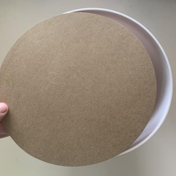
Now that you’ve chosen your pot we can move on to making some dirt. Start off by picking some thin cardboard, an empty cereal box or something similar will work well. Be careful not to use too thick of cardboard or this will make threading your wires more difficult later on. With your pot facing down, trace around the opening of the pot onto the cardboard in order to get an accurate measurement to cut out and act as our base.
How exactly you choose to make your dirt is up to you and your skill level. I made a large swatch of punch-needled fabric which I then wrapped around my cardboard and hot glued in place. If you want to do something more simple or less time-consuming, you can also glue down yarn straight onto the cardboard or wrap the board in brown fabric such as felt. I chose to punch needle my dirt because I thought it provided an interesting texture, but you can get creative with how you want your soil to look.
After you’ve decorated your cardboard base it may no longer fit perfectly into the base of the pot. This can easily be fixed by slowly trimming small sections of your dirt off until it once again fits snuggly in your pot. If through this trimming process any of your chosen dirt material comes loose, simply attach the edges back down with hot glue.
As one final step in getting our dirt in place, cut out, bend, and attach small pieces of cardboard onto the inside of your pot to act as makeshift brackets to keep your dirt from tipping or slipping lower in the pot. I recommend putting your brackets at a level where your dirt can sit into the pot without any of the edges peeking out. These brackets don’t have to be perfect or incredibly strong either, a well-trimmed dirt base will do most of the work in holding itself in place, this is just an extra precaution.
Step 2: Growing Your Garden
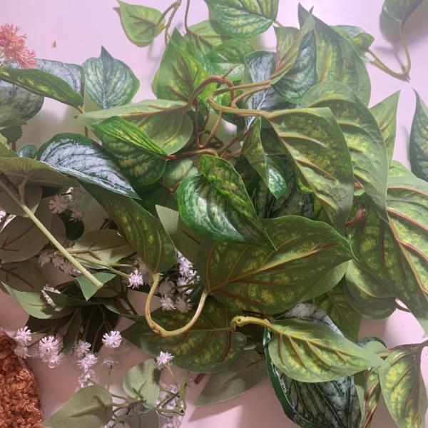
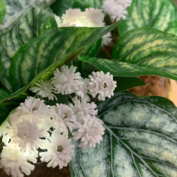
Next up it’s time to start adding some plants to our beautiful dirt. When picking your plants I would recommend picking one distinctive plant for each sensor or actuator you are planning to have. This not only adds variety to your garden but also makes the interactions more intuitive. I set mine up so that the large green leaves actuated a speaker when touched, the white flowers glowed, and the pink flowers held the photosensors which controlled the white flower’s brightness. Also when picking your plants, be sure to get enough to create a dense covering. Having enough plants is essential for hiding all of the wires embedded into the soil of our plant.
Once you’ve picked your plants you can start, well, planting! In order to make your plants sturdy in the soil, start by poking a hole in your dirt for the plant to go through. A punch needle tool is excellent for this job if you have one, but if not any kind of tool good at poking holes such as an awl or a knife will do (but be sure to pick something that you have good control over so you won’t risk cutting yourself!) Once you have your hole punched, add some hot glue to the base of the plant you’re embedding. Make sure to plant small sections at a time, this will make for easier planting and will give you more control over the layout of your garden. With the tip of your plant coated in hot glue, push the stem through the hole that you made! You don’t need to worry about pushing the stem all the way through your soil layer, you just need to get it deep enough to be sturdy once the hot glue dries.
As you continue this process slowly your garden will grow until you’ve created a beautiful botanical arrangement. When placing your plants, be sure to also think about how your plants are laid out in terms of their intended interactions. For example, the sensors in my pink flowers actuated the lights in my white flowers, so I made sure to have several bunches of white flowers around the pink flowers so that the cause and effect would be more clear.
Step 3: Creating Your Interactions
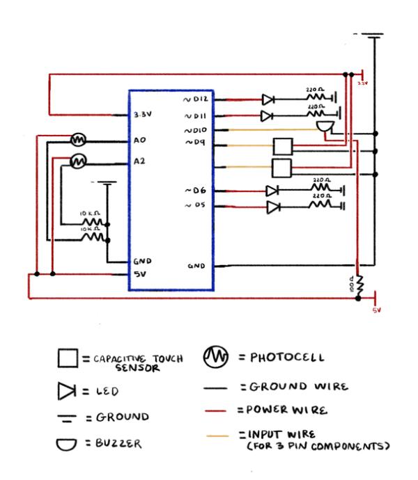
Your garden has been planted so now it’s time to bring it to life! You should already know what kind of interactions you have planned for your garden, but now it’s time to put those plans into action with circuitry and code. I recommend beginning by laying out all of your components in order to figure out what kind of wiring you need, and where each component should be connected to your microcontroller. For me, this meant planning the pin layout of my components based on whether they were digital or analog and whether or not they required Pulse Width Modulation (PWM). The capacitive touch sensors and buzzer for the leaves would only be turned on or off and required no PWM, so I designated digital pins for these components. The photocells would be taking in a wide range of inputs and would write a fluctuating brightness to the LEDs, so the photocells needed to be attached to analog pins, and the LEDs needed to be connected to digital pins capable of PWM (marked by a “~” on most pinouts).
I began my circuit process by only connecting one of each component to make sure that my wiring and code worked. Once each interaction was working, I then moved on to adding to the interaction with more code and more components, but it’s always good to start small and work your way up in order to make debugging easier. I began setting up my components with jumper wires for ease of use and then later moved to soldering the components. Jumper wires work well for testing code and basic circuits, and they would certainly work for a complete project if you did not know how to solder. Soldering components however allows for greater flexibility and specificity which can make a project look cleaner and be easier to follow, especially when it comes to color coding your wires. I always designate my red wires as power and my black wires as ground, with either yellow or white wires as additional inputs if the component requires. You can follow whatever color code makes sense to you and works with your materials, but establishing a consistent color scheme makes following your connections that much easier. You can see my circuit diagram above, color-coded using this same system. Physical computing is that much harder because you have to troubleshoot both physical and digital elements, so it is essential when creating your interactions to have a clear sense of how your board is wired and where each component is hooked up.
Step 4: Making the Flowers Glow
With my pins set up it was time to start on the first interaction, making the flowers glow. I began by using code for photocells that was created by Adafruit as a reference tool. This code needed very little tweaking, and mainly just required adding additional LEDs and photocells, and adjusting the range of photocell values to match the ambient light in the room. Adjusting your photocell values can be tricky, so it’s easiest to print your photocell readings and then test it in ambient light and with your hand over it to get the most accurate range for the lighting in your area. I also added an if statement to the code which turned the LEDs off if the photocell readings fell below a certain value, this helped add to the effect that putting your hand over the pink flowers, where the photocells were, completely controlled the glowing of the white flowers.
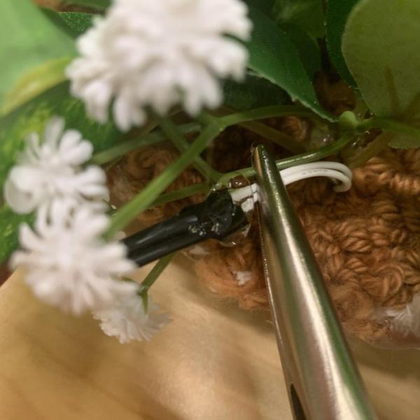
I ran the wires through the dirt using the same technique that was used to plant the flowers, punching a hole through the dirt, and then feeding each LED up through that hole and next to its respective flower plant. When wiring the LEDs, I used flexible silicon wire which I found very helpful in making the wires snake up next to the small flowers without being seen. In order to attach the LEDs to the flowers, I began by hot gluing the stem of the flower and the base of the LED together–I would recommend using pliers for this process to avoid burning your hand. Then, I added some hot glue to the bottom of the flower and pressed it onto the top of the LED. Once the LED and flower were dried together, I would then arrange the surrounding flowers to hide any extra wires that were poking out and to completely conceal the LED. When putting hot glue on your LEDs, the more glue you add the more the light will be diffused. I enjoyed this appearance because it gave more of a glowing effect than a sharp lighting effect, but if you are not looking for a more diffused light I would be careful with how much hot glue you use.
A very similar process was used to attach the photocells to the pink flowers, the only difference being that I bundled the flowers around the base of the photocell to prop it up and make sure it wouldn’t be covered, rather than intentionally trying to cover it with the flowers.
| int photocellPin1 = A0; |
| int photocell1; //on A0 |
| int photocellPin2 = A2; |
| int photocell2; |
| int LEDPin1 = 11; |
| int LEDPin2 = 6; |
| int LEDPin3 = 5; |
| int LEDPin4 = 12; |
| void setup() { |
| Serial.begin(9600); |
| pinMode(photocellPin1, INPUT); //photocell |
| pinMode(photocellPin2, INPUT); //photocell |
| pinMode(LEDPin1, OUTPUT); //LEDs |
| pinMode(LEDPin2, OUTPUT); //LEDs |
| pinMode(LEDPin4, OUTPUT); //LEDs |
| pinMode(LEDPin4, OUTPUT); //LEDs |
| } |
| void loop() { |
| //read inputs |
| photocell1 = analogRead(photocellPin1); //range: 14-660 |
| photocell2 = analogRead(photocellPin2); //range: 14-660 |
| //LED output |
| int LEDbrightness1 = map(photocell1, 500, 15, 0, 255); |
| int LEDbrightness2 = map(photocell2, 500, 15, 0, 255); |
| //turn LED off if bright |
| if(photocell1 < 500){ |
| analogWrite(LEDPin1,LEDbrightness1); |
| analogWrite(LEDPin2,LEDbrightness1); |
| } else{ |
| digitalWrite(LEDPin1, LOW); |
| digitalWrite(LEDPin2, LOW); |
| } |
| //turn LED off if bright |
| if(photocell2 < 500){ |
| analogWrite(LEDPin3,LEDbrightness2); |
| analogWrite(LEDPin4,LEDbrightness2); |
| } else{ |
| digitalWrite(LEDPin3, LOW); |
| digitalWrite(LEDPin4, LOW); |
| } |
| } |
Step 5: Making the Leaves Sing
The code for this part of the project looks like a lot, but it was actually pretty easy to write thanks to some very helpful resources. Buzzers are capable of playing different pitches based on the given frequency, and so if you provide them with an array of frequencies and tell them how to play through those frequencies, they can play a song. This incredible repository has a variety of different song files based on this principle. Each file defines every note as a frequency the buzzer can read, has the melody of the song written out as an array, and includes a function to run through this melody. For my project, I chose the Super Mario Bros Theme Song–specifically the game over theme–and a portion of the Mii Channel theme because they are short and recognizable, but you could use any song in this repository or even use the function and defined notes as a basis to write out a new melody. I used two different songs, and simply copied the player function into my own code, and changed out the sensor being used to actuate the buzzer in each function. Even though the code for both functions is nearly identical save for a few variable names, I separated them out into two different functions (Mario() and Mii()) for simplicity. I also pulled the notes, melodies, and global variables of these song functions out into a new reference sketch in order to keep the code in the main sketch as clean as possible. Once these songs were written into the program, the code for actuating them was a simple if statement that played the designated song depending on which sensor had been touched.
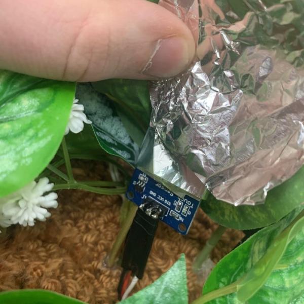
This interaction was quite a bit trickier because, in order for the project to look clean and believable, all of the sensors needed to be completely hidden under the leaves. I fed the wires for the sensors through the dirt like with the other components but I instead had to feed the wires back down through the hole I created rather than pushing the sensor up, simply because of the size of the component. Before attaching the sensor to the leaf, I first covered the touch part of the sensor in tinfoil. Tinfoil carries charge throughout its surface, and we can leverage this to make the area of the leaf that can be sensed even greater. You can actually even make your own capacitive touch sensors out of just tinfoil and a resistor if you’re interested. If you’re using a capacitive touch sensor like mine, however, be sure not to let the tinfoil touch the base of your wires or it will short your circuit, I recommend hot gluing or taping the base of the foil to the sensor in order to keep it from slipping down. In order to even further increase the surface area that could actuate the buzzer, I also expanded the tinfoil onto the underside of other leaves and then attached them to the original piece of foil using copper tape (which is also conductive). By carefully laying the network of foil out under many leaves, I was able to increase the area which was sensitive to touch while also hiding all of the foil by laying the leaves on top of one another to hide the foil. Luckily, though this is one of the more time-intensive component setups, the other part of this interaction–the buzzer–requires almost no additional setup besides getting the code ready.
You’ll need to test your individual buzzer to see how loud it is and how muffled you are okay with it being, but my buzzer was loud enough to be heard through some of the dirt so I didn’t have to worry about concealing it well. I simply made a small hole through the cardboard and some of the fabric at the center of the garden for the speaker to push through, and then hot glued the base of the buzzer that was left sticking out through the cardboard in order to keep it adhered to the board.
Source: Glowing Garden