Gliderscore is a program developed by Gerry Carter that not only scores a model plane flying competition, but provides timing for the various flying tasks
One feature of Gliderscore Timer is that it outputs a Serial ASCII string that contains the countdown time, the group , the round and whether it is working time or preparation time.
The above description really is only for the benefit of those who use this program
The Timing Board described here can be used for other purposes where serial data is to be displayed. I hope people can use my ideas for other projects.
The Timing Board described here receives Gliderscore serial data via a serial radio link (the serial link is described in another Instructable). It parses the serial data and displays it on a series of LEDs.
The Timing Board will display the Glider Timer clock (on the lower line); the round and group either setting up or flying. To indicate whether it is preparation time or working tme, the charaters will be lit red for preparation time and green/blue for working time.
The receiver is an HC12 transceiver module working in the 433Mhz ISM band. It requires no programming in order to work in this application.
The computing is done by an Arduino. This project has been designed around the Arduino Pro Mini, but an Arduino Uno or Arduino Micro (or any Arduino with at least 32kB of memory can be used)
The LEDs are generally known as WS2811. One can buy these on line from a number of suppliers. They come in strip form containing the WS2811 driver chip and three RGB LED chips in a section. The sections are usually sold in a continuous strip from one to 5 metres in length.
The WS2811 version was chosen for two reasons
a) The LEDs can be run directly from a 12 volt supply. That means a battery can be used to power the Timing Board. Running at 12 volts also means that the current carried by the strip PCB tracks is less (than running the system at 5 volts)
b) There is no need to address every LED. The character segments are formed from two sections ( making a segment length of 100mm) This also uses less program memory.
This is how I built the Timing Board. One can modify the dimensions to suit locally available materials.
The build consists of three parts
a) Building the back board
b) Sticking the LED segments to the board and wiring
c) Assembling the electronics and programming the Arduino
Whilst basic skills are required to make the Timing Board, and the project should work as described, in case where it is not working would require the use of voltmeters, oscilloscopes and logic probes which is being the scope of this Instructable.
Supplies
Backing board:
3mm or 4mm sheet. 610mm x 710mm Plywood or MDF or similar material
19mm x 19mm timber. 2.6 meters. Pine or similar timber.
One dimension of the above piece of timber needs to be close to 19mm. This affects the viewability of the characters.
Matt black paint. 250ml
Gloss paint . 250ml. This is the paint for the external finish. It can be any paint that you may have handy
4mm prismatic acrylic sheet. 610mm x 710mm This material is used as diffusers in lighting systems. It is available from local plastic sheet suppliers cut to size. The thickness is not as important as choosing a shhet that has at least 80% optical transmission
Wood glue
Nails 1mm x 15mm x 50
Screws x 25. 5g x 16mm, brass countersunk head
Tools to assemble Backing Board:
Saw
Hammer
Clamps
No 2 Philips screwdriver
Electric drill
1.5mm drill bit (1/16th inch)
3mm drill bit (1/8th inch)
Electronics:
Arduino Pro Mini. 5V version Any Arduino with at least 16kB of memory is suitable
WS2811 LED strip. 3.6 meters. IP30, 300 LED/5 meters, Black PCB. Available from online suppliers.
0.8mm x 5 meters copper wire unenammelled.
Black, White and Red insulated hook up wire. 3 meters of each
HC12 transceiver Available from online suppliers.
170mm 0.5mm diameter insulated wire (stiff)
Perforated copper strip board. 100mm x 100mm
2.5mm DC bulkhead Male connector
Tools to assemble Backing Board:
Soldering iron
Solder
Cutting pliers
Scissors
Cutting blade (no 11 Exacto blade)
Step 1: Backing Board
The backing board is easily made
Cut the 3mm sheet to 610mm x 710mm
Cut two lengths of the 19mm x 19mm timber to 710mm
Cut two lengths of the 19mm x 19mm timber to 572mm
Glue and nail the timber to the edge of the sheet. Use clamps to hold the timber whilst the glue dries
Paint the “inside’ of the backing board with the matt black paint
Paint the outside of the backing board with gloss paint.
The prismatic acrylic sheet can be fitted after the electronics are tested
The sheet is fastened by the timber screws around th perimeter at intervals of 100mm
Drill 1.5mm pilot holes through the acrylic sheet and into the timber.
Drill a 3mm clearance hole in the acrylic sheet for the screw
Step 2: LED Strips
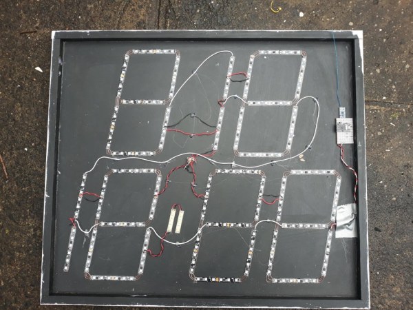
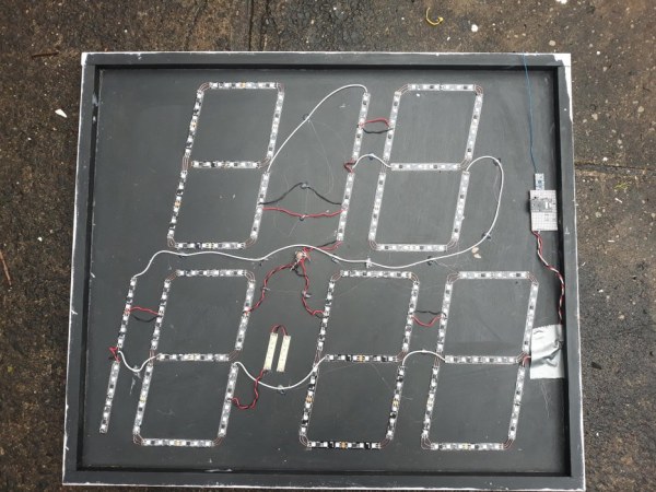
The general layout of the LED strips is shown in the file Large Layout
The LED strips are placed on the backing board and adhere via the sticky tape supplied on the strip
Apart from two characters that represent the number ‘1″, the other five characters are laid out in the form of a seven segment display
A template for each seven segment character is supplied in file Digit Template
I print out 7 of these (make sure that you print without any scaling).
Cut out with a hobby blade the areas where the LED strips will go. There are 7 places on each template to cut out – 100mm x 10mm
Use the digit templates to layout the characters on the backing board. Use masking tape to hold the templates temporarily
Cut the (long) LED strip into sections of two segments long. Each segment is 100mm long.
The LED segments will eventually make one long electrically continuous line. Use the diagram in drawing ZZZ as a guide . The starting LED segment is A and is followed by B, then C etc.
The LED segments have an arrow denoting the direction. Make sure that all segments have the arrows pointing in the direction of the end of the string.
Take off the adhesive backing paper and glue the segments on the backing board.
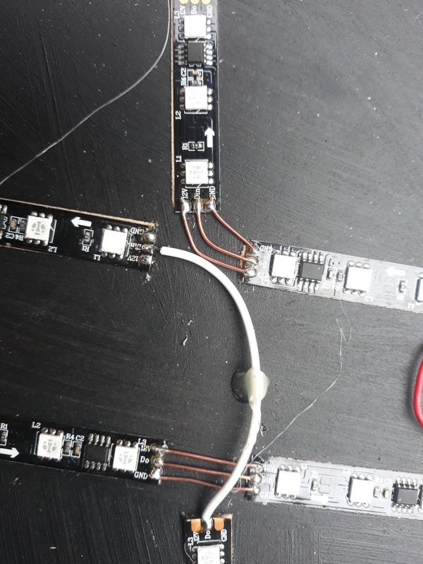
Use short lengths of the copper wire to join the 12V, D0-DI and GND pads of segments at the corners.
Use lengths of insulated wire to connect DO-DI between characters.
Drill the back of the backing board to accept the 2.5mm DC socket. Wire from the back of the socket the GND wire to each character and the 12V (positive) wire to each character. This is to make sure that the voltage drop is minimised to each character
Step 3: Electronics
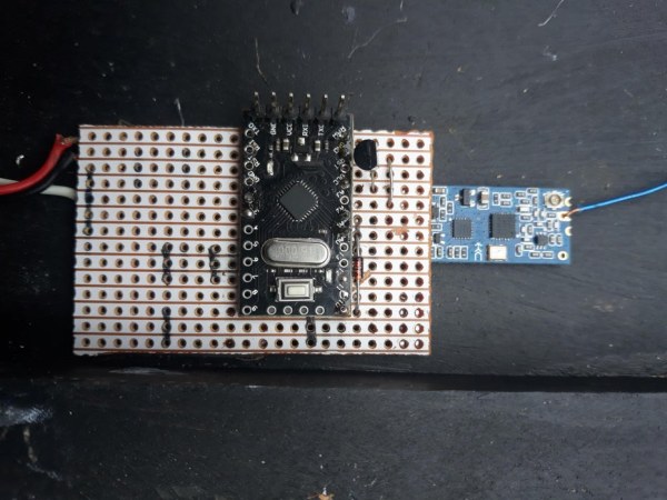
Wire up the Arduino and the HC12 module as per the attached schematic.
The schematic uses an Arduino Pro Mini and the pins used correspond to the Arduino sketch supplied.
If you are using a different Arduino then you will need to figure out which pins to use, and then modify the Arduino sketch.
The aerial for the HC12 module is a piece or single core insulated wire about 172mm long. You will need to solder this to the aerial pin
The Arduino and the HC12 module are connected via a perforated copper stripboard.
The default parameters of the HC12 module do not need to be changed.
Initial testing of the electronics
To program the Arduino Pro Mini, you will need to use an USB to serial converter.
Connect the Arduino Pro Mini through the USD to serial converter to the USB port of your computer
Test that you can download the blink sketch to the Arduino. If this is not possible trouble shoot the problem
(This Instructable is about the construction of the Timing Board. Any issues with the Arduino are able to be researched on line by reference to the Arduino site or to doing a search on line)
Attach the completed electronics to segment A of the backing board Its only three wires being 12V, GND and DI
Testing of the LEDs
Install the Adafruit Neopixel library
Open the example sketch called Strandtest
Change the LED count to 78 and the LED PIN to 2 (for an Arduino Pro Mini)Download and run the sketch.
At some stage all the LEDs should light.
If the LEDs light partially along the string, then either the power or the data connection is not continuous. It could also be caused by faulty WS2811 chips. In case of a faulty chip, it’s easier to replace that section of LED strip and retest.
Once you are satisfied that all the LEDs are operating correctly, you can install the Timing Board program onto the Arduino.
To test that it is operating correctly will require use of the compatible Timing transmitter (see the instructable)
Step 4: Conclusion
The supplied code, is I think, well documented
Anyone is invited to use the code and extend it for their use.
The Timing Board can be made larger by using more sections in series
The colour of the LEDs during working and preparation times can be changed as desired.
The Timing Board is designed to be powered by a nominal 12v supply. That means either a car battery or 3 cell LiPo or 4 cell LiFe batteries The current draw averages about 2.5 Amps.
The timing Board can be located up to about 100m from the compatible transmitter
There is no limit as to how many Timing and Information Boards are used, as unlike WiFi or Bluetooth, the boards are not bound to the transmitter.
Source: Gliderscore Timing Board