Summary of Exploring Arduino: LED Control using Rotary Encoder
This article details an Arduino project using a rotary encoder to control five colored LEDs (white, blue, green, yellow, red) via a 16x2 LCD display. It explains two circuit configurations: one with an I2C module and one without. The encoder's rotation selects the LED position, while pressing the knob toggles the selected LED on or off. The guide includes component lists, wiring diagrams for both setups, and complete code snippets for implementation.
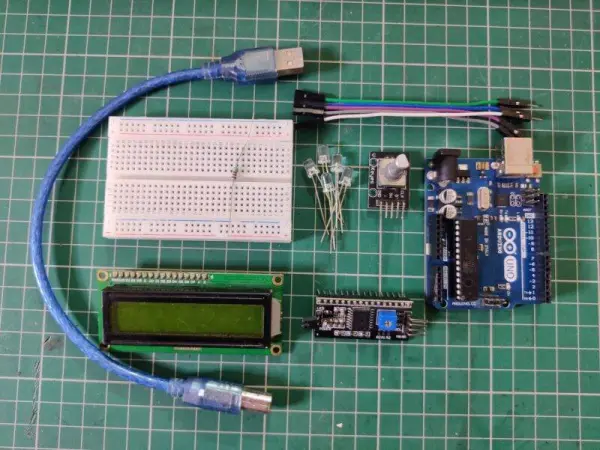
Parts used in the Arduino LED Project:
- Arduino UNO
- 16×2 LCD
- I2C module
- Breadboard and jumper wires
- LEDs of different colors (White, Blue, Green, Yellow, Red)
- Rotary Encoder
- USB cable
- 220 ohm resistors
Introduction
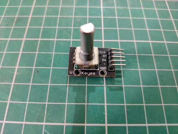
Hello everyone, welcome back to Techatronic. Within this article, we’ll be creating an Arduino LED project using a rotary encoder and a 16×2 LCD module. To ensure ease of understanding, we’ve included circuit diagrams and detailed connection descriptions for each setup. The rotary encoder comprises 5 pins, two for power and three for data. Its bi-directional rotation allows for control and selection of activities on the Arduino with LED. So, without further delay, let’s delve into this Arduino LED project. Also, explore our articles on IoT and basic electronics. Ensure accurate connections before uploading the provided code to the Arduino board.

Description
In the initial setup, which involves a basic rotary encoder project, rotating the encoder’s knob displays various position values on the Arduino serial monitor screen within the LED project. These values correspondingly increase or decrease based on the knob rotation.
Moving on to the second and third setups, both incorporate an LCD and LEDs connected to the Arduino LED circuit.
You have the option to identify and select a particular LED based on its position, visible on the LCD screen. In this Arduino LED project, simply choose the LED and press the rotary encoder’s knob. If the chosen LED was previously off, it will turn on, and conversely, if it was on, it will turn off. A state of 0 signifies the LED with Arduino is off, while 1 denotes it is on.
Rotating the knob of the rotary encoder adjusts the positional value, enabling you to designate the LED you wish to control. Furthermore, explore our creation of a music-reactive LED using Arduino for additional projects.
Components Required for arduino and LED
- Arduino UNO
- 16×2 LCD
- I2C module
- Breadboard and jumper wires
- LEDs of different colors
- Rotatory Encoder
- USB cable for uploading the code
Circuit for Arduino with LED Project
Circuit for Rotatory Encoder With Arduino
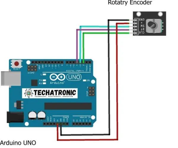
Subsequently, connect the GND pin of the rotary encoder to the Arduino’s GND pin.
Next, create connections by attaching the CLK and DT pins of the rotary encoder to the digital-2 and digital-4 pins of the Arduino.
Finally, complete the circuit by connecting the SW pin of the rotary encoder to the digital-3 pin of the Arduino.
Your circuit setup is now finished. Proceed by uploading the provided code below.
Code:
// TECHATRONIC.COM
int counter = 0;
int aState;
int aLastState;
const int RotaryCLK = 2; //CLK pin on the rotary encoder
const int RotaryDT = 4; //DT pin on the rotary encoder
const int RotarySW = 3; //SW pin on the rotary encoder
void setup()
{
pinMode (RotaryCLK,INPUT); // CLK PIN OF ROTATRY ENCODER
pinMode (RotaryDT,INPUT); // DT PIN OF ROTATRY ENCODER
Serial.begin (9600);
// Reads the initial state of the 2
aLastState = digitalRead(RotaryCLK);
}
void loop()
{
aState = digitalRead(RotaryCLK); // Reads the “current” state of the outputA
// If the previous and the current state of the 2 are different, that means a Pulse has occured
if (aState != aLastState){
// If the outputB state is different to the 2 state, that means the encoder is rotating clockwise
if (digitalRead(RotaryDT) != aState) {
counter ++;
} else {
counter –;
}
Serial.print(“Position: “);
Serial.println(counter);
}
aLastState = aState; // Updates the previous state of the 2 with the current state
}
Circuit Without I2C Module
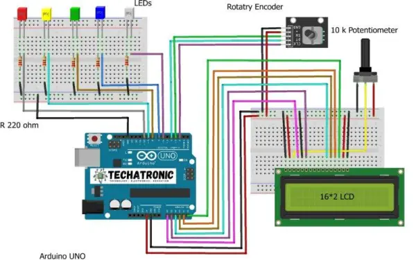
In this setup, we’re constructing the project without utilizing an I2C module. Begin by establishing connections between the pins of the 16×2 LCD and the analog pins of the Arduino according to the provided diagram. For a detailed reference on the connections or Arduino interfacing with LED, please refer to our article.
Utilize five LEDs of different colors and link their negative legs to the GND pin of the Arduino through a 220 ohm resistor. Connect the positive leg of the red LED to the digital-10 pin of the Arduino. Similarly, connect the positive legs of the yellow, green, blue, and white LEDs to the digital-9, digital-8, digital-7, and digital-6 pins of the Arduino, respectively.
Next, establish connections by linking the VCC pin of the rotary encoder to the 5-volt pin of the Arduino, and connect the GND pin of the rotary encoder to the GND pin of the Arduino. Wire the CLK and DT pins of the rotary encoder to the digital-2 and digital-4 pins of the Arduino. Lastly, connect the SW pin of the rotary encoder to the digital-3 pin of the Arduino.
Your circuit assembly is now complete. Proceed by uploading the provided code to your Arduino setup.
Code:
// TECHATRONIC.COM
#include “LiquidCrystal.h”
LiquidCrystal lcd(A0, A1, A2, A3, A4, A5);
// RS=A0, E=A1, D4=A2, D5=A3, D6=A4, D7=A5
const int RotaryCLK = 2; //CLK pin on the rotary encoder
const int RotaryDT = 4; //DT pin on the rotary encoder
const int RotarySW = 3; //SW pin on the rotary encoder (Button function)
int ButtonCounter = 0; //counts the button clicks
int RotateCounter = 0; //counts the rotation clicks
bool rotated = true; //info of the rotation
bool ButtonPressed = false; //info of the button
int CLKNow;
int CLKPrevious;
int DTNow;
int DTPrevious;
float TimeNow1;
float TimeNow2;
const int whiteLED = 6;
const int blueLED = 7;
const int greenLED = 8;
const int yellowLED = 9;
const int redLED = 10;
bool whiteLEDStatus = false;
bool blueLEDStatus = false;
bool greenLEDStatus = false;
bool yellowLEDStatus = false;
bool redLEDStatus = false;
void setup()
{
Serial.begin(9600);
lcd.begin(16,2);
lcd.setCursor(0,0); //Defining position to write from first row, first column .
lcd.print(“W B G Y R POS”);
lcd.setCursor(0,1); //second line, 1st block
lcd.print(“0 0 0 0 0 0”); //You can write 16 Characters per line .
delay(3000); //wait 3 sec
pinMode(2, INPUT_PULLUP);
pinMode(3, INPUT_PULLUP);
pinMode(4, INPUT_PULLUP);
pinMode(whiteLED, OUTPUT); //white LED
pinMode(blueLED, OUTPUT); //blue LED
pinMode(greenLED, OUTPUT); //green LED
pinMode(yellowLED, OUTPUT); //yellow LED
pinMode(redLED, OUTPUT); //red LED
digitalWrite(whiteLED, LOW);
digitalWrite(blueLED, LOW);
digitalWrite(greenLED, LOW);
digitalWrite(yellowLED, LOW);
digitalWrite(redLED, LOW);
CLKPrevious = digitalRead(RotaryCLK);
DTPrevious = digitalRead(RotaryDT);
attachInterrupt(digitalPinToInterrupt(RotaryCLK), rotate, CHANGE);
attachInterrupt(digitalPinToInterrupt(RotarySW), buttonPressed, FALLING); //either falling or rising but never “change”.
TimeNow1 = millis(); //Start timer 1
}
void loop()
{
printLCD();
ButtonChecker();
}
void buttonPressed()
{
//This timer is a “software debounce”. It is not the most effective solution, but it works
TimeNow2 = millis();
if(TimeNow2 – TimeNow1 > 500)
{
ButtonPressed = true;
}
TimeNow1 = millis(); //”reset” timer; the next 500 ms is counted from this moment
}
void rotate()
{
CLKNow = digitalRead(RotaryCLK); //Read the state of the CLK pin
// If last and current state of CLK are different, then a pulse occurred
if (CLKNow != CLKPrevious && CLKNow == 1)
{
// If the DT state is different than the CLK state then
// the encoder is rotating CCW so increase
if (digitalRead(RotaryDT) != CLKNow)
{
RotateCounter++;
if(RotateCounter > 4)
{
RotateCounter = 0;
}
}
else
{
RotateCounter–;
if(RotateCounter < 0)
{
RotateCounter = 4;
}
}
}
CLKPrevious = CLKNow; // Store last CLK state
rotated = true;
}
void printLCD()
{
if(rotated == true) //refresh the CLK
{
lcd.setCursor(12,1);
lcd.print(RotateCounter);
Serial.println(RotateCounter);
rotated = false;
}
}
void ButtonChecker() //this is basically the menu part. keep track of the buttonpressed and rotatecounter for navigation
{
if(ButtonPressed == true)
{
switch(RotateCounter)
{
case 0:
if(whiteLEDStatus == false)
{
whiteLEDStatus = true;
digitalWrite(whiteLED, HIGH); //white LED is turned ON
}
else
{
whiteLEDStatus = false;
digitalWrite(whiteLED, LOW); //white LED is turned OFF
}
lcd.setCursor(0,1); // Defining positon to write from second row, first column .
lcd.print(whiteLEDStatus);
Serial.println(whiteLEDStatus);
break;
case 1:
if(blueLEDStatus == false)
{
blueLEDStatus = true;
digitalWrite(blueLED, HIGH);
}
else
{
blueLEDStatus = false;
digitalWrite(blueLED, LOW);
}
lcd.setCursor(2,1); // Defining positon to write from second row, first column .
lcd.print(blueLEDStatus);
break;
case 2:
if(greenLEDStatus == false)
{
greenLEDStatus = true;
digitalWrite(greenLED, HIGH);
}
else
{
greenLEDStatus = false;
digitalWrite(greenLED, LOW);
}
lcd.setCursor(4,1); // Defining positon to write from second row, first column .
lcd.print(greenLEDStatus);
break;
case 3:
if(yellowLEDStatus == false)
{
yellowLEDStatus = true;
digitalWrite(yellowLED, HIGH);
}
else
{
yellowLEDStatus = false;
digitalWrite(yellowLED, LOW);
}
lcd.setCursor(6,1); // Defining positon to write from second row, first column .
lcd.print(yellowLEDStatus);
break;
case 4:
if(redLEDStatus == false)
{
redLEDStatus = true;
digitalWrite(redLED, HIGH);
}
else
{
redLEDStatus = false;
digitalWrite(redLED, LOW);
}
lcd.setCursor(8,1); // Defining positon to write from second row, first column .
lcd.print(redLEDStatus);
break;
}
}
ButtonPressed = false; //reset this variable
}
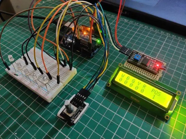
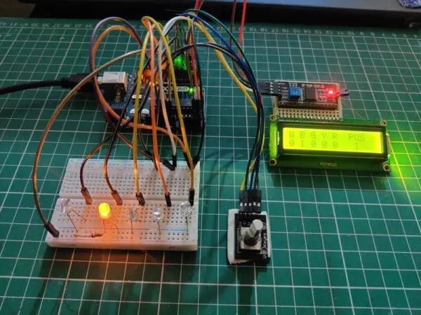
Circuit with I2C module
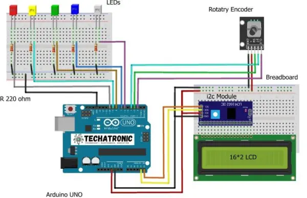
In this setup, we’re constructing a project utilizing an I2C module. Begin by connecting the VCC pin of the I2C module to the Arduino’s 5-volt pin and linking the GND pin of the I2C module to the Arduino’s GND pin.
Proceed by joining the SDA pin of the module to the Arduino’s analog-4 pin and attaching the SCL pin of the module to the Arduino’s analog-5 pin. Follow the diagram for proper connections between the pins of the 16×2 LCD and the I2C module.
Utilize LEDs of five distinct colors, connecting their negative legs to the Arduino’s GND pin via a 220-ohm resistor. Connect the positive leg of the red LED to the digital-10 pin of the Arduino. Similarly, link the positive leg of the yellow, green, blue, and white LEDs to the digital-9, digital-8, digital-7, and digital-6 pins of the Arduino, respectively.
Subsequently, connect the VCC pin of the rotary encoder to the Arduino’s 5-volt pin and link the GND pin of the rotary encoder to the Arduino’s GND pin. Then, attach the CLK and DT pins of the rotary encoder to the digital-2 and digital-4 pins of the Arduino. Connect the SW pin of the rotary encoder to the digital-3 pin of the Arduino.
Following these steps completes the circuit setup. Now, please upload the provided code.
Code:
// TECHATRONIC.COM
// I2C LIBRARY
//https://github.com/fdebrabander/Arduino-LiquidCrystal-I2C-library
#include
#include LiquidCrystal_I2C lcd(0x3F,16,2);
// SDA = A4
// SCL = A5
const int RotaryCLK = 2; //CLK pin on the rotary encoder
const int RotaryDT = 4; //DT pin on the rotary encoder
const int RotarySW = 3; //SW pin on the rotary encoder (Button function)
int ButtonCounter = 0; //counts the button clicks
int RotateCounter = 0; //counts the rotation clicks
bool rotated = true; //info of the rotation
bool ButtonPressed = false; //info of the button
int CLKNow;
int CLKPrevious;
int DTNow;
int DTPrevious;
float TimeNow1;
float TimeNow2;
const int whiteLED = 6;
const int blueLED = 7;
const int greenLED = 8;
const int yellowLED = 9;
const int redLED = 10;
bool whiteLEDStatus = false;
bool blueLEDStatus = false;
bool greenLEDStatus = false;
bool yellowLEDStatus = false;
bool redLEDStatus = false;
void setup()
{
Serial.begin(9600);
lcd.init(); // Arduino
// lcd.begin(); // nodemcu
lcd.backlight();
lcd.setCursor(0,0); //Defining position to write from first row, first column .
lcd.print(“W B G Y R POS”);
lcd.setCursor(0,1); //second line, 1st block
lcd.print(“0 0 0 0 0 0”); //You can write 16 Characters per line .
delay(3000); //wait 3 sec
pinMode(2, INPUT_PULLUP);
pinMode(3, INPUT_PULLUP);
pinMode(4, INPUT_PULLUP);
pinMode(whiteLED, OUTPUT); //white LED
pinMode(blueLED, OUTPUT); //blue LED
pinMode(greenLED, OUTPUT); //green LED
pinMode(yellowLED, OUTPUT); //yellow LED
pinMode(redLED, OUTPUT); //red LED
digitalWrite(whiteLED, LOW);
digitalWrite(blueLED, LOW);
digitalWrite(greenLED, LOW);
digitalWrite(yellowLED, LOW);
digitalWrite(redLED, LOW);
CLKPrevious = digitalRead(RotaryCLK);
DTPrevious = digitalRead(RotaryDT);
attachInterrupt(digitalPinToInterrupt(RotaryCLK), rotate, CHANGE);
attachInterrupt(digitalPinToInterrupt(RotarySW), buttonPressed, FALLING); //either falling or rising but never “change”.
TimeNow1 = millis(); //Start timer 1
}
void loop()
{
printLCD();
ButtonChecker();
}
void buttonPressed()
{
//This timer is a “software debounce”. It is not the most effective solution, but it works
TimeNow2 = millis();
if(TimeNow2 – TimeNow1 > 500)
{
ButtonPressed = true;
}
TimeNow1 = millis(); //”reset” timer; the next 500 ms is counted from this moment
}
void rotate()
{
CLKNow = digitalRead(RotaryCLK); //Read the state of the CLK pin
// If last and current state of CLK are different, then a pulse occurred
if (CLKNow != CLKPrevious && CLKNow == 1)
{
// If the DT state is different than the CLK state then
// the encoder is rotating CCW so increase
if (digitalRead(RotaryDT) != CLKNow)
{
RotateCounter++;
if(RotateCounter > 4)
{
RotateCounter = 0;
}
}
else
{
RotateCounter–;
if(RotateCounter < 0)
{
RotateCounter = 4;
}
}
}
CLKPrevious = CLKNow; // Store last CLK state
rotated = true;
}
void printLCD()
{
if(rotated == true) //refresh the CLK
{
lcd.setCursor(12,1);
lcd.print(RotateCounter);
Serial.println(RotateCounter);
rotated = false;
}
}
void ButtonChecker() //this is basically the menu part. keep track of the buttonpressed and rotatecounter for navigation
{
if(ButtonPressed == true)
{
switch(RotateCounter)
{
case 0:
if(whiteLEDStatus == false)
{
whiteLEDStatus = true;
digitalWrite(whiteLED, HIGH); //white LED is turned ON
}
else
{
whiteLEDStatus = false;
digitalWrite(whiteLED, LOW); //white LED is turned OFF
}
lcd.setCursor(0,1); // Defining positon to write from second row, first column .
lcd.print(whiteLEDStatus);
Serial.println(whiteLEDStatus);
break;
case 1:
if(blueLEDStatus == false)
{
blueLEDStatus = true;
digitalWrite(blueLED, HIGH);
}
else
{
blueLEDStatus = false;
digitalWrite(blueLED, LOW);
}
lcd.setCursor(2,1); // Defining positon to write from second row, first column .
lcd.print(blueLEDStatus);
break;
case 2:
if(greenLEDStatus == false)
{
greenLEDStatus = true;
digitalWrite(greenLED, HIGH);
}
else
{
greenLEDStatus = false;
digitalWrite(greenLED, LOW);
}
lcd.setCursor(4,1); // Defining positon to write from second row, first column .
lcd.print(greenLEDStatus);
break;
case 3:
if(yellowLEDStatus == false)
{
yellowLEDStatus = true;
digitalWrite(yellowLED, HIGH);
}
else
{
yellowLEDStatus = false;
digitalWrite(yellowLED, LOW);
}
lcd.setCursor(6,1); // Defining positon to write from second row, first column .
lcd.print(yellowLEDStatus);
break;
case 4:
if(redLEDStatus == false)
{
redLEDStatus = true;
digitalWrite(redLED, HIGH);
}
else
{
redLEDStatus = false;
digitalWrite(redLED, LOW);
}
lcd.setCursor(8,1); // Defining positon to write from second row, first column .
lcd.print(redLEDStatus);
break;
}
}
ButtonPressed = false; //reset this variable
}
About the Code
Initially, we set up a counter variable and set its initial value to 0. Subsequently, we specify the three pins used by the rotary encoder. Within the loop function, we continuously monitor the rotation of the rotary encoder and display the current position value. In relation to the LEDs, we additionally verify whether the user has pressed the button. If the button is pressed at a particular position, the corresponding device will toggle on or off according to the prevailing conditions.
- How does the rotary encoder control the LEDs?
Rotating the knob adjusts a positional value displayed on the LCD, allowing you to select a specific LED. - What happens when the rotary encoder knob is pressed?
Pressing the knob toggles the state of the currently selected LED; if it is off, it turns on, and vice versa. - Can this project be built without an I2C module?
Yes, the article describes a setup where the LCD connects directly to Arduino analog pins instead of using an I2C module. - Which Arduino pins are used for the rotary encoder CLK and DT pins?
The CLK pin connects to digital-2 and the DT pin connects to digital-4. - How many LEDs are used in this project?
Five LEDs of different colors are used: white, blue, green, yellow, and red. - What is the function of the SW pin on the rotary encoder?
The SW pin acts as a button that must be pressed to toggle the selected LED. - Where should the negative legs of the LEDs be connected?
The negative legs connect to the GND pin through a 220 ohm resistor. - What library is required for the I2C version of the project?
The LiquidCrystal_I2C library is included for the setup utilizing the I2C module. - How does the LCD display the LED status?
The LCD shows the status as 0 for off and 1 for on at specific column positions corresponding to each color. - What is the purpose of the software debounce timer in the code?
The timer ensures the button press is registered correctly by waiting 500 milliseconds before setting the flag.