Summary of DIY Solar Panel Monitoring System – V1.0
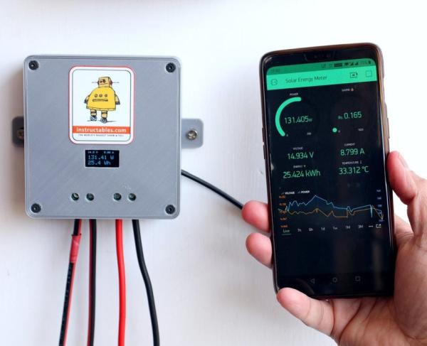
This article details the construction of a DIY solar monitoring system using an ESP32 board to track voltage, current, and temperature. The project enables both local display via an OLED screen and remote monitoring through the Blynk app on smartphones. It explains sensor interfacing, circuit design for voltage/current division, and PCB fabrication to provide real-time data on solar production and energy savings.
Parts used in the Solar Monitoring System:
- ESP32 Board (30 pins)
- ACS723 Sensor
- OLED Display
- Resistors
- Ceramic Capacitors
- XL7015 Buck Converter Module
- Temperature Sensor (DS18B20)
- Screw Terminal 3P (3.5mm pitch)
- Screw Terminal 2P (9.52mm pitch)
- Header Pins
- Jumper Wires M-F
- PCB
- Soldering Flux
- Soldering Paste
A few months back, I have installed a small-scale Off-Grid Solar System. I am always very curious to see the performance of my solar PV system, and the good news is that the charge controller that I am using has its own local display for monitoring. But, I am badly missing the remote monitoring facility. So, I have decided to make my own monitoring system which must have both local and remote monitoring facilities.
Why We Need Monitoring?
1. It gives clear information about various solar parameters, extracted energy, fault detection, historical analysis of the solar plant, and associated energy loss.
2. You can easily measure your solar production and the saving on your monthly electricity bill.
3. You can track all the important parameters of the solar PV system in real-time from your smartphone.
In this Instructables, I will show you I have made a simple Solar Monitoring System by using an ESP32 development board and ACS723 current sensor.
Specification:
1. Input Voltage – 0- 24V ( Can be extended up to 50V )
2. Input Current: 0 -15A
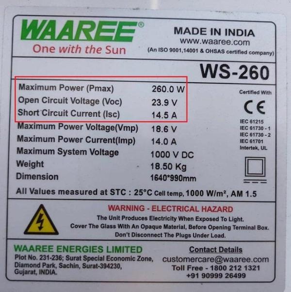
3. Solar Panel Rating – 250W (12V ) / 500W ( 24V )
Visit my newly created personal Blog: https://www.opengreenenergy.com
Full Video Tutorial:
Supplies:
Components Used:
1. ESP32 Board – 30 pins ( Banggood / Aliexpress )
2. ACS723 Sensor ( LCSC )
3. OLED Display ( Amazon / Banggood )
4. Resistors ( Amazon / Banggood )
5. Ceramic Capacitors ( Amazon / Banggood )
6. XL7015 Buck Converter Module ( Amazon )
7. Temperature Sensor ( Amazon / Banggood )
8. Screw Terminal 3P- 3.5mm pitch ( LCSC )
9. Screw Terminal 2P – 9.52mm pitch (LCSC )
10. Header Pins ( Amazon / Banggood )
11. Jumper Wires M-F ( Amazon )
12. PCB
13. Soldering Flux ( Banggood )
14. Soldering Paste ( Banggood )
Tools Used:
1. Soldering Iron ( Amazon / Banggood )
2. Nipper ( Amazon / Banggood)
3. Wire Stripper ( Amazon / Banggood)
4. 3D Printer ( Amazon / Banggood)
Step 1: How It Works?
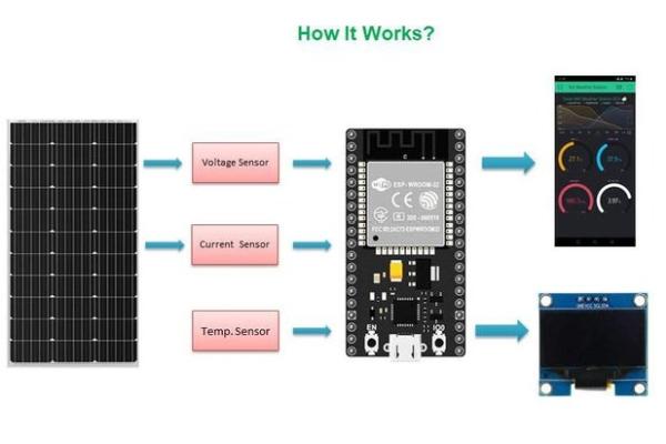
The Solar panel voltage and current are sensed by voltage and current sensor respectively. Here, a voltage divider network is used to measure the solar panel voltage, and the AC723 hall effect current sensor is used to measure the solar panel current. Similarly, the ambient temperature is sensed by the DS18B20 temperature sensor.
The raw sensor data from all the sensors are processed by an ESP32 board and do all the necessary maths to calculate the power, energy. The processed data then send to an OLED display for local monitoring and also to the cloud for remote monitoring. The remote monitoring is done through the Blynk app installed on a Smartphone.
Step 2: Measuring Voltage
The solar panel voltage is sensed by a voltage divider network consists of two resistors R1=47k and R2=6.8k. The output from the R1and R2 is connected to ESP32 analog pin GPIO pin 34. The output from the voltage divider is smoothed out by using a ceramic capacitor C1.
Voltage Measurement :
ESP32’s analog inputs can be used to measure DC voltage between 0 and 3.3V. The solar panel that I have considered can generate 24V ( Open Circuit Voltage). To read this voltage we have to step don the voltage which can be done by using a voltage divider network.
For a voltage divider circuit
Vout = R2/(R1+R2) x Vin
Vin = (R1+R2)/R2 x Vout
The analogRead() function reads the voltage and converts it to a number between 0 and 4095
Calibration :
We’re going to read the output value with one of the analog inputs of Arduino and its analogRead() function. That function outputs a value between 0 and 4095 that is 3.3/4095 for each increment
Vin = Vout*(R1+R2)/R2 ; R1=47k and R2=6.8k
Vin= ADC count * ( 3.3/4095 ) * ( ( 47+6.8) / 6.8 ) Volt
You can use solar panel with higher voltage by selecting the appropriate resistors R1 and R2.
To select the voltage divider resistance values, you can use this online calculator.
Step 3: Measuring Current
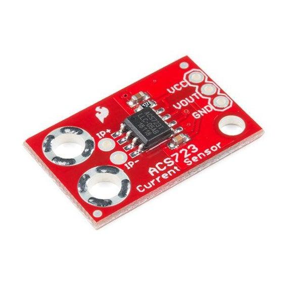
For current measurement, I used a Hall Effect current sensor ACS 723 -20AUvariant. There are other variants of ACS723 Sensor based on the range of its current sensing. The ACS712 sensor reads the current value and converts it into a relevant voltage value, The value that links the two measurements is Sensitivity. The output sensitivity can be obtained from the datasheet. As per the datasheet, the sensitivity is 200mV / A
Calibration:
analog read value = analogRead(Pin);
ADCVoltage = (3.3/4095)*analog read value
Current in amp = ( ADCVoltage – Offset Voltage ) / sensitivity
As per data sheets offset voltage is 0.1 * Vcc ( 0.5V ) and sensitivity is 200mV/A
Note: The output from the ACS723 is stepdown by a voltage divider network consists of R4 and R5.
Step 4: Measuring Temperature
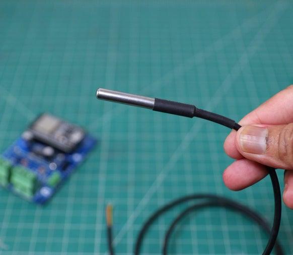
I have used an external DS18B20 probe for measuring the ambient temperature. It uses a one-wire protocol to communicate with the microcontroller. One-wire devices need a pull-up resistor connected to their signal line to be properly read by your board. Here, I have used a 4.7K resistor ( R6 ) as a pull-up resistor.
It can be hooked up to the PCB through the 3pin screw terminal.
To interface with the DS18B20 temperature sensor, you need to install the One Wire library and the Dallas Temperature library. You can read this article for more details on the DS18B20 sensor.
The connection is as follows:
Red Wire -> Vcc
Yellow Wire -> DATA
Black Wire -> GND
All the above are clearly labeled on the PCB for avoiding any confusion.
Step 5: Interfacing OLED Display
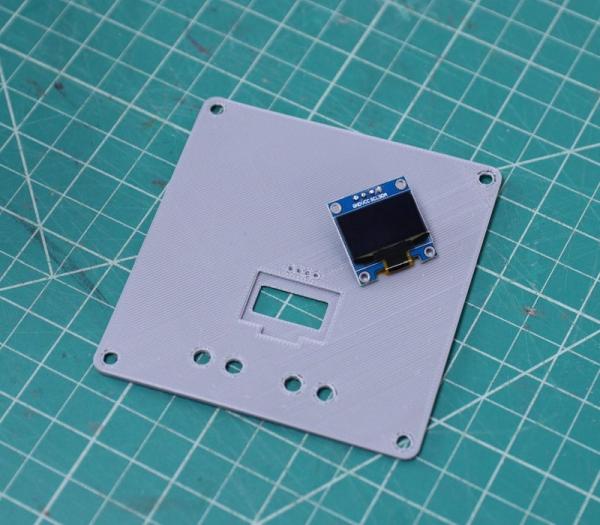
To display the solar panel parameters locally, I have used a 0.96″ OLED display. It has a 128 x 64 resolution and uses an I2C bus to communicate with the ESP32. Two pins SCL (GPIO22), SDA (GPIO21) in ESP32 are used for communication.
I am using the Adafruit_SSD1306 library to display the parameters. First, you have to download the Adafruit_SSD1306. Then installed it.
The connections should be as follows:
ESP32 – ->OLED
3.3V —>VCC
GND –>GND
GPIO21—-> SDA
GPIO22—-> SCL
Step 6: PCB Design
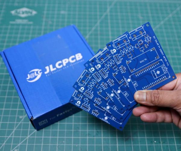
I have drawn the schematic by using EasyEDA online software and then designed a custom PCB for this project. The PCB is designed for mounting the different modules instead of using a lot of components. I have ordered my PCB from JLCPCB and received it within 7 days.
Source: DIY Solar Panel Monitoring System – V1.0
- How is the solar panel voltage measured?
A voltage divider network consisting of two resistors (R1=47k and R2=6.8k) steps down the voltage to be read by the ESP32 analog pin. - Can I use a solar panel with higher voltage?
Yes, you can select appropriate resistor values for R1 and R2 to accommodate higher voltages up to 50V. - What sensor is used to measure current?
The ACS723 Hall Effect current sensor is used to measure the solar panel current. - How is the ambient temperature sensed?
An external DS18B20 probe is used, communicating via a one-wire protocol with a 4.7K pull-up resistor. - Which library is required for the OLED display?
The Adafruit_SSD1306 library is used to interface with the 0.96-inch OLED display. - How is remote monitoring achieved?
Remote monitoring is performed through the Blynk app installed on a smartphone. - What tool was used to design the custom PCB?
The schematic was drawn using EasyEDA online software before designing the custom PCB. - What are the input specifications for this system?
The system supports an input voltage of 0-24V (extendable to 50V) and an input current of 0-15A.