Summary of DIY Programming Cable Using Arduino Uno – Baofeng UV-9R Plus
This guide shows how to convert a Baofeng UV-9R headphone/earpiece cable into a programming cable using an Arduino UNO as a USB-serial adapter, covering disassembly, re-pinning the connector PCB for RXD/TXD/GND, soldering jumper wires, placing the UNO in reset mode, and using CHIRP to read and program radio channels. It warns about driver/software compatibility and gives testing tips and troubleshooting for common errors.
Parts used in the Baofeng UV-9R Programming Cable:
- Baofeng UV-9R (or UV-9R Plus) radio
- Baofeng UV-9R headphone / earpiece cable (connector assembly)
- Arduino UNO with USB cable
- 3 or 4 male-to-male jumper cables
- Soldering iron and solder
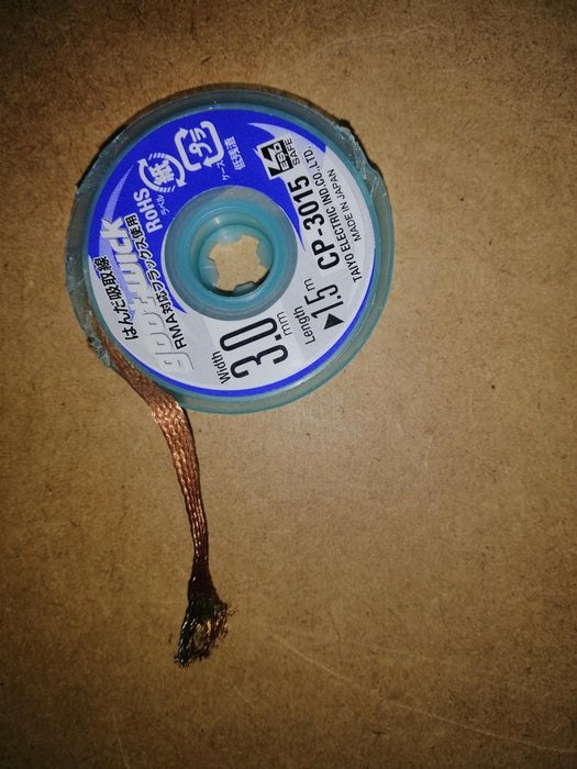
- Solder wick (optional, recommended)
- Multimeter
- Computer (Windows or Mac recommended) with Arduino drivers
- CHIRP software

Hey Everyone, this is a simple guide on how to convert your Baofeng UV-9R (or plus) Headphone / ear piece cable into a programming cable using an Ardunio UNO as a USB Serial Converter.
[DISCLAIMER] I do not take any responsibility in any damage caused to your radio or computer, or any other property or person. Only use this guide as a reference. FOLLOW at own RISK.
This guide is based off a similar Instructable for the UV-5R, which can be found here.
The fitting required I believe was initially used by Motorola in the DP4XXX Series (However it could’ve been used else where).
You will need to also install Ardunio usb drivers (at a minimum), and also Chirp (software for programming your UHF). I found that Chirp did not work on Linux (ubuntu 20) as it was still using python2 which has since be deprecated. Recommend Windows OR Mac computer.
Initially I attempted this using a off brand Arduino NANO, however the board did not work with Chirp.
Supplies
Here are the basic items you will need:
- 1x Baofeng UV-9R (or plus)
- 1x Baofeng UV-9R Headphone / Ear piece cable
- 1x Soldering Iron + solder
- 1x Solder Wick – OPTIONAL (Highly recommended)
- 4x male to male jumper cables
- Ardunio UNO + USB cable
- Windows / Mac computer (Chirp did not work on Ubuntu 20)
Step 1: Taking Apart the Head Phone / Ear Piece
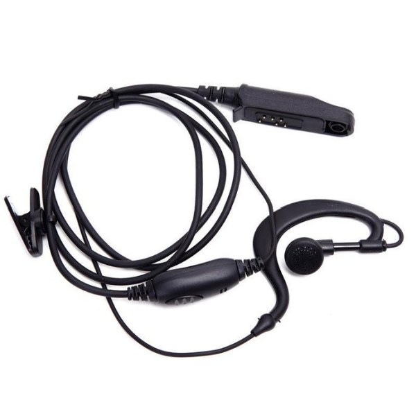
Apologies i did not take photos of the cable before disassembly.
1. However, using a flat head screw driver remove the rubber cover on the ear piece connector. You should now see a gap where you can pry out the plastic cover and circuit board.
Don’t be afraid of damaging the wires as they will need to be remove anyway.
2. Once the circuit board has been removed, continue removing the cable from the connector housing. You will need to remove all the cable so that you can use the hole to insert the new wires in later steps (jumper cables in the instance).
3. You should now have the following:
- 1x Connector housing
- 1x Circuit board (Should have 6 pins attached)
- 1x Pin / circuit board cover
- 1x Connector rubber cover (this is no longer required)
- 1x Headphone / ear piece cable (this is no longer required)
Step 2: Re-pinning Circuit Board
You should now have a circuit board with 6 pins attached. All pins will need to be remove besides 1. This one pin that will not be remove is the GND or ground pin.
You will need to remove 5 pins, it is recommended that you use a solder wick to absorb the solder when removing the pins.
Once all 5 pins have been removed you will only need to re-solder 2 pins. On the circuit board you will see two holes with the markings RXD & TXD (TXD is next to the GND pin). Using your soldering iron and solder, add the two new pins into the RXD & TXD holes.
Step 3: Soldering Jumper Cables
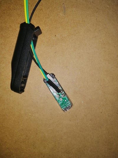
Now you should have a circuit board with 3 pins attached, these three pins should be RXD, TXD, GND.
Using 3 of your 4 jumper cables you will need to solder them to the pins, make sure you take note of what color jumper cables you used. Personally, I like to use black for the ground (GND) pin where possible. It is also recommended you tin the pins on the jumper cables with solder before soldering to circuit board.
Once complete, run your jumper cables through your connector housing and clip the connector shut (you may need to modify the housing if you have any clearance issues, just make sure the connector will still fit properly to your UV-9R).
My pin to jumper cable reference table:
– GND -> Black
– RXD -> Yellow
– TXD -> Green
Yours may be different so make sure you take note of what you used and adjust this guide accordingly.
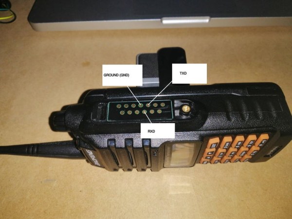
How to test your connections:
1. Connect the cable to your radio
2. Using a multi-meter (set to read voltage), connect the GND jumper cable to the negative multi-meter probe, and the positive to either the RXD or TXD jumper cables (you will need to test both). Both jumper cables should be reading around 3.8v.
*make sure you use the screw to fasten the connector to the radio.
Step 4: Setting Up Arduino UNO to Connector
Now that your connector is wired up and still attaches to your radio, its time to connect it to your Arduino UNO.
Initial i did attempt this with an off brand Arduino NANO, however it did not preform as expected.
Using the pin to jumper cable color chart i made earlier, attach the cables to the UNO:
– Black -> GND
– Yellow -> RXD
– Green -> TXD
Now as we are only using the arduino as a usb serial converter, we will need to put the UNO in ‘RESET MODE’.
Using your 4th jumper cable, find the pin holes on the UNO for GND & RST / RESET. Bridging these two pins puts the UNO in reset mode (prevents any loaded code from running).
Step 5: Connecting the UNO to Your Computer & Running Chirp
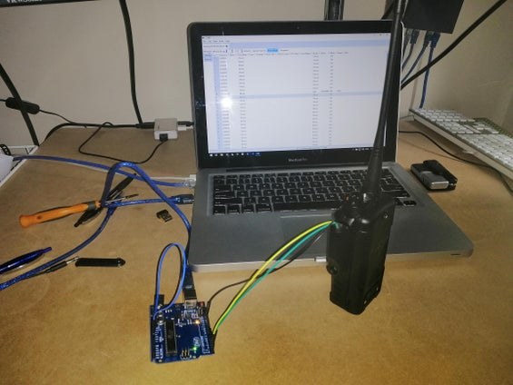
Now that all our connectors are in place, and all our software has been added to our computer, it’s time to plug in our UNO for the first time.
1. Plug in the UNO to your computer (UNO should have a red light)
2. Open Chirp
3. Connect the programming cable to your UV-9R (Don’t turn the radio on yet).
4. Inside Chirp, from the top menu select Radio > Download from Radio
5. You should be prompted with a few drop downs:
– Port : [This is unique to your setup e.g. COM* ]
– Vendor: Baofeng
– Model: UV-9R (This also includes UV-9R Plus)
6. Turn the radio on, and then click OK in Chirp
Chirp should then go into ‘Cloning’ mode and then display a table of all channels that already exist on your radio
* If you are getting an error ‘An Error has occurred. Not the amount data we want’ – this usually is an issue with the cable, check make sure all your connectors are setup properly, or try a different UNO board.
*make sure you use the screw to fasten the connector to the radio.
Step 6: Programming UHF Channels
If you are using this as a UHF radio 400-500MHZ, you can now find a list of your local channels and frequencies to upload to you radio. The import / export format is CSV. I recommend first exporting a CSV from your radio and then reusing the same CSV columns when importing the new channels.
Hopefully all works out and you can now program your new radio!
Source: DIY Programming Cable Using Arduino Uno – Baofeng UV-9R Plus
- Can I use an Arduino UNO as a USB serial converter for the UV-9R?
Yes; put the UNO in reset mode (bridge GND and RST) and wire RXD, TXD, and GND from the connector to the UNO. - What parts do I need to make the programming cable?
The guide lists the UV-9R radio, its headphone cable connector, Arduino UNO and USB cable, jumper wires, soldering iron and solder, optional solder wick, multimeter, and CHIRP on a Windows or Mac computer. - Which pins on the connector PCB are required?
You need RXD, TXD, and GND; remove the other pins and resolder pins into the RXD and TXD holes. - How do I test the wiring before using CHIRP?
Use a multimeter: connect negative probe to GND and positive to RXD or TXD; both should read around 3.8 V when plugged into the radio. - Does CHIRP work on Linux (Ubuntu 20) according to the guide?
The author found CHIRP did not work on Ubuntu 20 due to Python2 dependency and recommends Windows or Mac. - What should I do if CHIRP shows an error about data amount?
That error usually indicates a cable issue; check connectors and wiring or try a different UNO board. - Can I use an off-brand Arduino Nano instead of an UNO?
The author attempted using an off-brand Nano but it did not perform as expected; UNO is recommended. - How do I prevent the UNO from running uploaded code?
Bridge the UNO GND and RST pins with a jumper to keep it in reset mode so it acts only as a USB-serial converter. - How should I map jumper wire colors to pins?
The author used Black for GND, Yellow for RXD, and Green for TXD but advises noting whichever colors you choose. - What format does CHIRP use to import/export channel lists?
CHIRP uses CSV format for import and export of channel lists.