Summary of DIY Multi Featured Robot With Arduino
This article details the construction of "BLUE ROVIER 316," a custom Arduino robot designed for voice recognition, gesture control, remote operation, and obstacle avoidance. Built from scratch to maximize learning, it utilizes an Android phone via Bluetooth as its primary interface. The project combines various functionalities into one unique device, overcoming hardware limitations like limited memory on the Arduino Uno through careful component selection and coding.
Parts used in the BLUE ROVIER 316:
- Android system
- Arduino Uno
- wtv020-sd-16p module and 8ohm speaker
- 2x L293d motor controller circuit
- 4x bo motors and wheels
- HC SR04 ultrasonic sensor
- 9g servo
- 8 AA battery holder and batteries
- 1gb micro SD card
- small switch box for chassis
- HC 05 Bluetooth Module
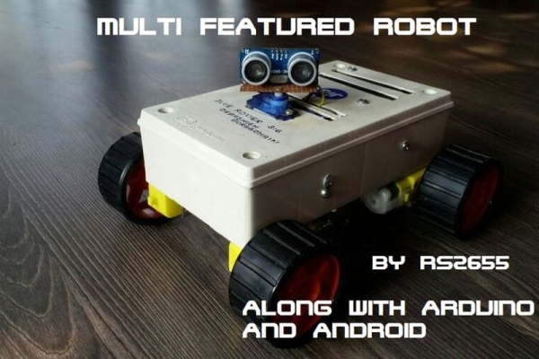
This robot was mainly built for understanding Arduino and combining various projects of Arduino to form a Multi Featured Arduino Robot. And further, who doesn’t want to have a pet robot? So I named it BLUE ROVIER 316. I could have bought a beautiful tracked chassis but making it from scratch teaches you more and gives you more pride after you have completed it.
The robot is capable of understanding voice commands, answering simple questions, controlling as an RC car and even avoiding obstacles while moving. It is mainly controlled through an Android phone which is connected to it through Bluetooth. Based on Android features such as Google Voice Recognition and Tilt sensing, it can really behave like a cute, smart robot. I added BLUE in its name because it is mainly based on Bluetooth. It was actually my first Arduino project and I wanted it to be unique .
If you like the project, please do vote for me in the Robotics Contest !
Step 1: Demonstration Video
You can watch the demo of the robot at this site:
Step 2: Story of ROVIER
You can jump to the next step if you do not want to go through the cute little story of BLUE ROVIER 316.
About a year back, I received an Arduino UNO as a gift from my father. Since it was my first step in the field of Arduino, I wanted to create something different and unique from the general Arduino projects. It needed to be a cute and smart robot which can understand Voice commands and do many more intelligent things such as Remote Control, Following Lines, Avoiding Obstacles and so on. The question was how to combine them together. And after surfing the net for a really nice time, I concluded that Bluetooth would be the cheapest mode. And so, BLUE ROVIER was set into motion.
But a situation arose where I had to exclude many features of the robot which I had expected it to posses, mainly because of the lack of memory on the Arduino UNO (even the less number of the digital pins on the UNO). Doesn’t matter, I proceeded. It took me really a good time to create the final version of the Robot. And so after many trials and failures, BLUE ROVIER finally came into being.
And so now on we can move to the making of the robot.
Step 3: Components and Parts

You will need just the following components:
1. Android system
2. Arduino Uno
3. wtv020-sd-16p module and 8ohm speaker
4. 2x L293d motor controller circuit
5. 4x bo motors and wheels
6. HC SR04 ultrasonic sensor
7. 9g servo
8. 8 AA battery holder and batteries
9. 1gb micro SD card
10. small switch box for chassis.
11. HC 05 Bluetooth Module
I know it looks costly! But don’t worry, it will only cost about two or three thousand rupees. Talking about the Android, it won’t be a great issue to posses one because most have it nowadays. But having newer versions (above 5.0) might increase the performance.
Try to buy motors having moderate rpm (60 to 100). This would help to keep the speed of the robot under control, as no other speed control circuit is installed. And 8 aa batteries are enough to power the robot for a good time. And considering the Bluetooth, HC 05 is suitable for the robot because it is cheap enough, and the performance is outstanding too.
The 1 GB micro SD card is needed to store voice files which are played when any question is asked to the robot [ Discussed in detail in the later part of the intstructable ]. The other components are discussed in detail in their respective step.
Now let’s move onto some simple “Theories” that are used in this robot.
Step 4: Voice Control Theory
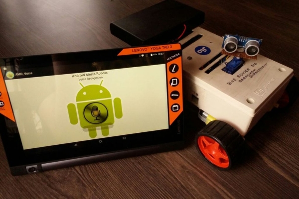
The robot can understand voice commands through an android phone. I guess everyone is familiar with Google Voice Recognition, the feature in Android where we say the word and Google types it.
The same feature is used here for recognising voice commands and converting them into text commands. The app here converts speech to text through Google and sends it to the robot through Bluetooth. The robot is programmed to follow these commands received through Bluetooth. It is also capable of answering a good number of questions. You can even add some more commands in the code to make the robot do some more awesome things.
Step 5: Gesture Control Theory

The gesture control or motion control mode is also done through the Android. In this mode, the robot can be controlled as an RC car by using the Android as the steering wheel. There is a sensor called “Accelerometer” in all Androids which is used in this mode. This accelerometer can determine the angle at which the phone is titled by measuring the acceleration forces acting on the Android. It is this sensor that makes the Android rotate its screen when we tilt the phone. The app here uses the phone accelerometer to determine the angle at which the phone is tilted. Then a character (A, B….) is sent to the robot through Bluetooth. The arduino is programmed to work according to the data received.
If the phone is tilted ahead, character A is sent and robot moves forward. When tilted back, character B is sent and the robot moves backward and so on for left and right. When the Android is placed horizontally, the character E is sent and the robot stops moving.
Step 6: Bluetooth Control Theory

In this mode,the robot works as a general RC car. Nothing new in this mode, it is just the same as a general remote controlled car available in the market, the only difference being that we are using an Android app to control the robot.
There are different buttons in the app, each having different characters associated with it. When any key is touched, a character is sent to the robot through Bluetooth, just like the gesture control mode. Further, the same characters are sent when the respective keys are touched, and the robot follows the incoming characters.
I have used the 360 and -360 degree buttons in the app to make the robot look right and left. You can change it in the code if you want to make the robot do some other things.
Step 7: Obstacle Avoidance Theory
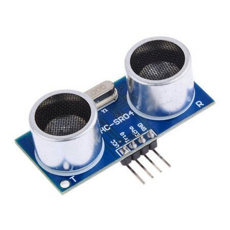
In this mode, the robot works as an Obstacle Avoidance robot, preventing itself from colliding with any object. This is done with the HC SR04 sensor.
I guess you know about SONAR (Sound Navigation And Ranging). The HC SR04 sensor continously emits ultrasonic sound waves. These waves get bounced back after striking a solid surface and come back to the sensor. The time taken by the waves to come back to the sensor is recorded.
Since sound travels at 340 m/s approximately and we know that SPEED × TIME = DISTANCE, we can determine the distance ahead.
For example, if the sound takes 2 seconds to come back, we can determine the distance through the above formula i.e. 340 × 2 = 680 m. This is how the robot can measure the distance ahead of it through the sensor.
While moving, the robot continuously measures the distance ahead through the sensor. If it senses that the clear space ahead of it is less than 30 cm, it stops moving.
Then it looks left and right and compares the distance of each side. If the left side has a greater distance, the robot turns left. Else if the right side is greater, the robot turns right. If both sides have equal distances, the robot turns back. This simple mechanism helps the robot to avoid the obstacles.
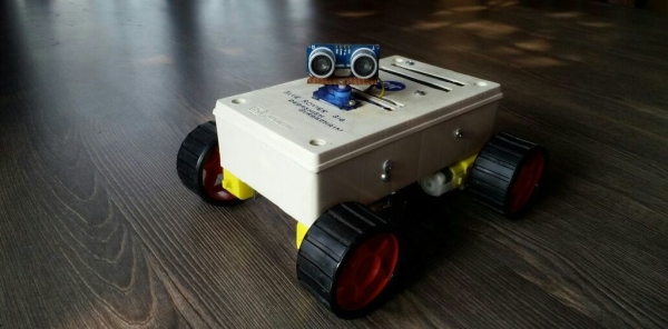
Step 8: Assembling the Chassis
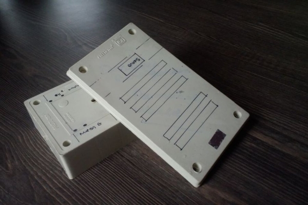
Making the chassis on your own, you must be very careful about the measurements and alignments. I chose to do so because I couldn’t find one on the net that satisfied me.
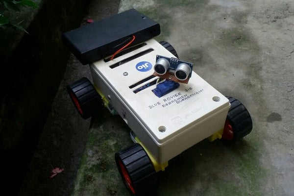
A general switch box used for power supply purposes is being used as the chassis. I guess, you can easily get one from an electrical appliance store. Firstly, attach the four motors at the bottom with some glue or clamps and then attach the wheels. Then you have to make the head of the robot (the servo and HC SR04 sensor).For the head, cut a small piece of perfboard and attach it to the servo through a screw. Then attach the ultrasonic sensor to the perfboard with some glue. Cut a small square hole at the top of the box and fix the servo in it.
Then attach the battery holder at the back of the robot through a screw. Put the circuits and the other components inside the box and your chassis is ready. Don’t forget to make some holes in front of the speaker for the sound to come out and produce a better quality.
Step 9: Preparing the Voice Module
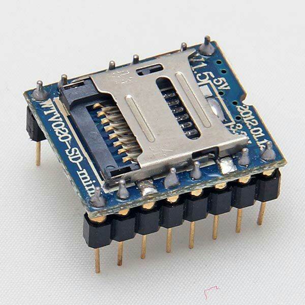
The speaking mode of the robot is fulfilled by the WTV 020 SD module. The module is used to play voice files for the robot. When any question is asked, the arduino will make the module play the respective voice file in the SD card. There are four serial data lines on the module for communicating with the arduino, the reset, clock, data and busy pins.
Remember that the names of the files should be in decimal (0001, 0002…). And that the files should either be in AD4 or WAV format. Further the module works only on a 1gb micro SD card. Some modules even work on 2gb cards and the card can hold a maximum of 504 voice files. So you can include a good number of voice files to play for a good number of questions.
You can even make your own voice AD4 files ( You can skip this part if you can adjust with the voice files provided along with this intstructable ).
Firstly, you must have two softwares, a sound editing software and a software called 4D SOMO TOOL which would convert the files to the AD4 format. Secondly, you have to prepare the Robot Voices. You can either convert text to speech or even record your own voice and make the Robot voices. Both of these can be done in the Sound Editing Software. But surely, robots do not look good if they speak human voices. So it should be better to convert text to speech. There are various engines like Microsoft Anna and Microsoft Sam your Computer that would help to do this.
After preparing the voice files, you have to save it in 32000 Hz and in the WAV Format. This is because the module can play voice files upto 32000 Hz. Then use the 4D SOMO TOOL to convert the files to the AD4 format. To do so, just open the SOMO TOOL, select the files, and click AD4 Encode and your voice files are ready. You can check the picture above for reference.
Read more: DIY Multi Featured Robot With Arduino
- How does the robot understand voice commands?
The Android app uses Google Voice Recognition to convert speech to text and sends the commands to the robot via Bluetooth. - Can I control the robot using gestures?
Yes, the robot can be controlled as an RC car by tilting the Android phone, which uses the accelerometer to send movement characters. - What is the best way to power the robot?
Eight AA batteries are used in a battery holder to provide sufficient power for the robot to run for a good time. - Does the robot avoid obstacles automatically?
Yes, the HC SR04 sensor measures distance; if space ahead is less than 30 cm, the robot stops and turns based on side distances. - What type of files are needed for the voice module?
The WTV 020 module requires voice files named in decimal format (e.g., 0001) in either AD4 or WAV format. - Why was the name BLUE ROVIER chosen?
The name includes BLUE because the robot is primarily based on Bluetooth technology. - Can I use a 2GB SD card with this module?
Some modules work on 2GB cards, but this specific project specifies that the module works only on a 1GB micro SD card. - How do I create custom voice files for the robot?
You can record your own voice or use text-to-speech engines, save them at 32000 Hz in WAV format, and convert them using 4D SOMO TOOL. - What software is required to make the robot speak?
You need sound editing software and 4D SOMO TOOL to prepare and convert audio files to the required AD4 format.