Summary of Digital Dice With Arduino
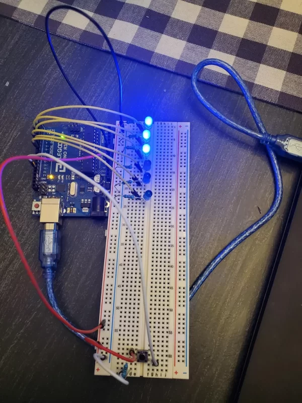
This beginner Arduino project enables users to create a digital dice that randomly generates numbers 1 through 6 using LEDs. By pressing a push button, the system illuminates specific LEDs corresponding to the rolled number, replacing physical dice with an electronic alternative powered by an Arduino Uno and basic circuit components.
Parts used in the Digital Dice:
- 6 LEDs
- 6 220 ohm resistors
- 1 push button
- 1 k-ohm resistor
- 1 Arduino Uno
- 1 breadboard
- jumper wires
Have you ever tried to play a game only to find out you don’t have any dice? That’s not a problem anymore! Now you can create your very own digital dice using LEDs and your Arduino board. This is a beginner-level project. This project will allow you to push a button and randomly generate a number between 1 and 6, shown with the number of LED lights.
Credits to:
EvdS. (n.d.). Led dice. Arduino Project Hub. Retrieved May 14, 2022, from https://create.arduino.cc/projecthub/EvdS/led-dice-885cf1?ref=tag&ref_id=led&offset=8
Supplies
6 LEDs
6 220 ohm resistors
1 push button
1 k-ohm resistor
1 Arduino Uno
1 breadboard
jumper wires
Step 1: Set Up the LEDs and Button
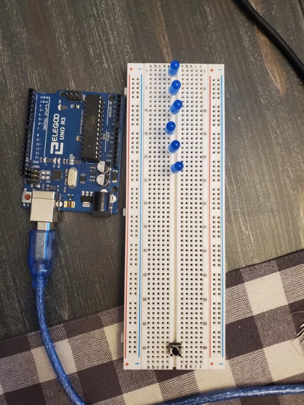
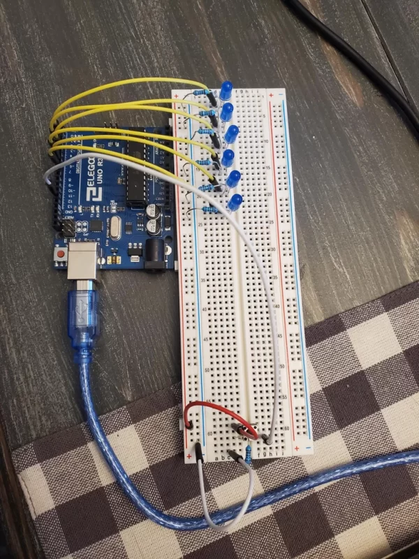
- Place the 6 LEDs in the breadboard as shown. They should go in rail E with two spaces in between each LED. You should place the Anode end (long end) of the LED in the first of the two spaces and the Cathode end (short end) in the second space. Place your LED Anode ends in rows 3, 7, 11, 15, 19, and 23.
- Place your button in the breadboard as shown. The left side should go in rail E, space 59 and 61, and the right side should go in rail F, space 59 and 61.
Step 2: Attach the Resistors
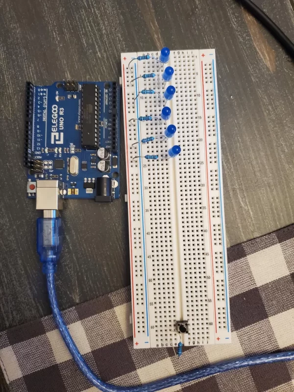
- Place a 220 ohm resistor in the row with the Cathode end of the LED. It should reach from rail D to the ground rail (-, blue) in each of the LEDs (rows 4, 8, 12, 16, 20, and 24).
- Place a 1 k-ohm resistor near your button. It should go from the bottom left of the button (row 61) to row 64.
Step 3: Wire the LEDs
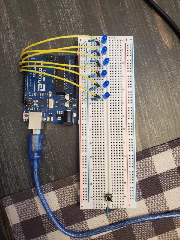
- Take one jumper wire and attach it from the Anode end of the first LED (row 3) and attach it to the digital output on the Arduino at space 2.
- Take the next jumper wire and attach it from the Anode end of the second LED (row 7) and attach it to the digital output on the Arduino at 3.
- Take the next jumper wire and attach it from the Anode end of the third LED (row 11) and attach it to the digital output on the Arduino at space 4.
- Take the next jumper wire and attach it from the Anode end of the fourth LED (row 15) and attach it to the digital output on the Arduino at space 5.
- Take the next jumper wire and attach it from the Anode end of the fifth LED (row 19) and attach it to the digital output on the Arduino at space 6.
- Take the next jumper wire and attach it from the Anode end of the sixth LED (row 23) and attach it to the digital output on the Arduino at space 7.
Step 4: Wire the Button
- Take one jumper wire and attach it on the bottom right (row 61, rail G) by the button. Attach the other end of the wire to the digital output on the Arduino at space 12.
- Take another jumper wire and attach it next to the resistor in the space at row 64, rail C. Attach the other end to the ground rail (-, blue).
- Take another jumper wire and attach it to the top left side of the button (row 59, rail D). Attach the other end to the positive rail.
Step 5: Attach the Ground and 5V Wire
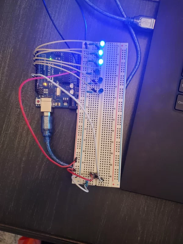
- Take a jumper wire and attach it to the Ground port on the Arduino. Attach the other end to the ground rail on the breadboard.
- Take another jumper wire and attach it to the 5V port on the Arduino. Attach the other end to the positive rail.
Source: Digital Dice With Arduino
- How many LEDs are required for this project?
The project requires exactly 6 LEDs. - What is the function of the push button?
Pressing the button triggers the random generation of a number between 1 and 6. - Which resistor value connects to the LED cathodes?
A 220 ohm resistor is placed in the row with the Cathode end of each LED. - Where should the LED Anode ends be placed on the breadboard?
Anode ends go in rows 3, 7, 11, 15, 19, and 23 within rail E. - Which Arduino digital pins connect to the LEDs?
The LEDs connect to digital outputs at spaces 2, 3, 4, 5, 6, and 7. - What role does the 1 k-ohm resistor play?
The 1 k-ohm resistor connects from the bottom left of the button to row 64. - How is the button wired to the Arduino?
One wire connects the bottom right of the button to digital output space 12. - Which power rails must be connected to the Arduino?
The Ground port connects to the ground rail and the 5V port connects to the positive rail.