Security is a major concern in our day to day life, and digital locks have became an important part of these security systems. One such digital code lock is imitated in this project using arduino board and a matrix keypad.
Components
- Arduino
- Keypad Module
- Buzzer
- 16×2 LCD
- BC547 Transistor
- Resistor (1k)
- Bread board
- Power
- Connecting wires
In this circuit we have used multiplexing technique to interface keypad for input the password in the system. Here we are using 4×4 keypad which contains 16 key. If we want to use 16 keys then we need 16 pin for connection to arduino but in multiplexing technique we need to use only 8 pin for interfacing 16 keys. So that it is a smart way to interface a keypad module. [Also check: Keypad Interfacing with Arduino]
Multiplexing Technique: Multiplexing technique is a very efficient way to reduce number of pins used with the microcontroller for providing input or password or numbers. Basically this technique is used in two ways – one is row scanning and other one is colon scanning. But in this arduino based project we have used keypad library so we do not need to make any multiplexing code for this system. We only need to use keypad library for providing input.
Circuit Description
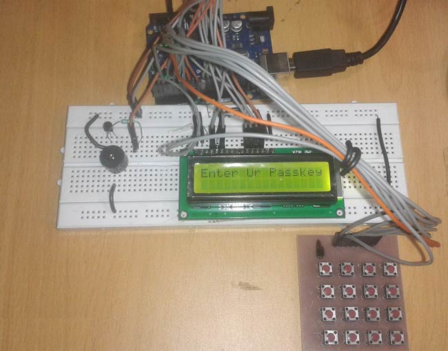
Circuit of this project is very simple which contains Arduino, keypad module, buzzer and LCD. Arduino controls the complete processes like taking password form keypad module, comparing passwords, driving buzzer and sending status to LCD display. Keypad is used for taking password. Buzzer is used for indications and LCD is used for displaying status or messages on it. Buzzer is driven by using a NPN transistor. Keypad module’s Column pins are directly connected to pin 4, 5, 6, 7 and Row pins are connected to 3, 2, 1, 0 of arduino uno. A 16×2 LCD is connected with arduino in 4-bit mode. Control pin RS, RW and En are directly connected to arduino pin 13, GND and 12. And data pin D4-D7 is connected to pins 11, 10, 9 and 8 of arduino. And one buzzer is connected at pin 14(A1) of arduino through a BC547 NPN transistor.
Keypad module’s Column pins are directly connected to pin 4, 5, 6, 7 and Row pins are connected to 3, 2, 1, 0 of arduino uno. A 16×2 LCD is connected with arduino in 4-bit mode. Control pin RS, RW and En are directly connected to arduino pin 13, GND and 12. And data pin D4-D7 is connected to pins 11, 10, 9 and 8 of arduino. And one buzzer is connected at pin 14(A1) of arduino through a BC547 NPN transistor.
Working
We have used inbuilt arduino’s EEPROM to save password, so when we run this circuit first time program read a garbage data from inbuilt arduino’s EEPROM and compare it with input password and give a message on LCD that is Access Denied because password does not match. For solving this problem we need to set a default password for the first time by using programming given below:
for(int j=0;j<4;j++)
EEPROM.write(j, j+49);
lcd.print("Enter Ur Passkey:");
lcd.setCursor(0,1);
for(int j=0;j<4;j++)
pass[j]=EEPROM.read(j);
This will set password “1234” to EEPROM of Arduino.
After running it first time we need to remove this from program and again write the code in to the arduino and run. Now your system will run fine. And for your second time used password is now “1234”. Now you can change it by pressing # button and then enter your current password and then enter your new password.
When you will enter your password, system will compare your entered password with that password that is stored in EEPROM of arduino. If match is occurred then LCD will show “access granted” and if password is wrong then LCD will “Access Denied” and buzzer continuously beep for some time. And buzzer is also beep a single time whenever user will press any button from keypad.
Read More: Digital Code Lock using Arduino