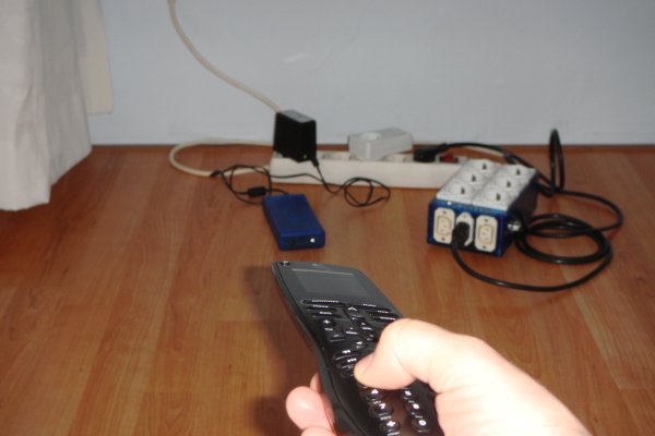
In this project we will show you how to switch on and off the power sockets box with an IR remote. Not only the power sockets box, but other RF receivers can be switched on and off with the same IR remote as well. We used the RF remote switch library from Randy Simons http://randysimons.nl/ to control the RF part. This library supports different types of RF receivers. The receivers we are using besides the power sockets box are from ELRO. We named this new box the IR2RF box. See this movie:
How does it work
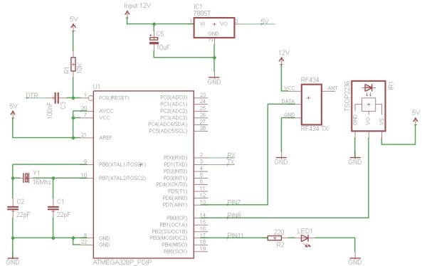
The IR2RF box translates the incoming infrared signals to 434Mhz Radio Frequentie (RF) signals. The RF part is switching the power sockets on and off. To get this working we have to connect one IR receiver (the TSOP2236) to the Arduino loaded microcontroller. For sending RF signals we connect the RF Link Transmitter to the microcontroller. See the wiring diagram below.
 Instead of using the Arduino Uno we only used the microcontroller and the necessary parts to get it working like an Arduino Uno. The reason for this is nothing more than saving space and costs. If you do choose to use an Arduino Uno then only connect the RF434 transmitter and TSOP2236 IR receiver. If you like you can add the LED1 with the R2 resistor, but the Arduino Uno already has a LED build on pin 13. The last thing needed is a 12 volt power supply for the RF434 transmitter. The RF transmitter will work with 5 volt, but the signal distance will be shorter. If you use a separate 12 volt power supply then don’t forget to connect the ground from the Arduino Uno with the ground of that 12 volt power supply.
C1,C2 and Y1 are generating a clock signal for the Atmega328 to get all the instructions synchronized. C3 is only needed for programming the Atmega328. Connect the DTR to the FTDI programmer. If you use a different programmer without an option for DTR then connect a push button between the reset pin and ground. Press this button when uploading your sketch to the microcontroller. R1 is a pull-up resistor to get the reset pin to 5 volt, but with protection against too much current (specially needed when using a pushbutton for reset). IC1 is a voltage regulator to provide a steady 5 volt. If you use the Arduino Uno then there is no need for this, because you can get 5 volt from the Arduino Uno.
How to get the IR codes with the TSOP2236 or TSOP2238
To play with an IR code we have to get it first. To do that we need to use a remote that will be recognized by the IR library to begin with. The supported types of remotes can be found in the IRremoteInt.h file in the library. In our case we used a MS-tech IR remote control. We programmed this remote in the Logitech Harmony One. This remote is programmable so you can program it with almost every type or remote that exists in the market. Every button pressed on the IR remote sends a particular code. We need to compare these codes with the coded values inside the IR2RF box. If the code matches we send an RF signal to switch a power socket on or off. To get these codes corresponding to buttons from our IR remote we have to use the sample code IRrecvDemo from the IRremote library. Load this code into the Arduino Uno or Atmega328. Also set the correct pin you use for the receiver. In our case.
|
1
|
const int RECV_PIN = 8; //pin for the IR receiver |
and watch the output from every button you press on the “serial monitor” in the Arduino Software. See here how the Arduino monitor looks like when pressing the buttons 1-9 and the ‘0’ and the’ok’ button at the IR remote.
As you can see the first code we received is 0xFFF807. I pressed the number one on my remote at that time so this code represents the number one from the IR remote. This value converted to decimal is 16775175. The reason I converted this is because in used the decimal values already in the power sockets box before and like to keep all the hard coded values in decimal. As you can see I receive the IR code first followed by 0xFFFFFFFF. This second code is always “0xFFFFFFFF” and therefore not interesting for this project. In the below source code we deal with unwanted codes:
|
1
|
if (results.value != 0xFFFFFFFF) |
in the source code we basically say if the received code is 0xFFFFFFFF we skip the checking procedure else we check if we have a match with one of the IR codes.
The arduino source code for translating the TSOP2216 codes to RF434
In this code we wait until we receive an Infrared command. As soon as we get an IR code we check if it matches one of our IR remote control buttons. If so we switch a power socket on or off followed by a blinking LED. This LED is for indicating an IR code is received so we don’t have to press the button again. The rest of the source code is explained by comments in the source code below.
|
1
2
3
4
5
6
7
8
9
10
11
12
13
14
15
16
17
18
19
20
21
22
23
24
25
26
27
28
29
30
31
32
33
34
35
36
37
38
39
40
41
42
43
44
45
46
47
48
49
50
51
52
53
54
55
56
57
58
59
60
61
62
63
64
65
66
67
68
69
70
71
72
73
74
75
76
77
78
79
80
81
82
83
84
85
86
87
88
89
90
91
92
93
94
95
96
97
98
99
100
101
102
103
104
105
106
107
108
109
110
111
112
113
114
115
116
117
118
119
120
121
122
123
124
125
126
|
/* * This code uses Ken Shirriff IRremote library * http://arcfn.com * and RemoteSwitch library v2.2.1 (20120314) made by Randy Simons http://randysimons.nl/ * This code is written to be used together with the power sockets box */ //USE THIS TOGETHER WITH POWER SOCKETS BOX VERSION 1.5#include // lib for the IR codes#include // lib for the RF codes//Elro RF keys in decimalconst long RF1_VALUE = 158186; //CODE ELRO REMOTE SWITCH SET 1,4 AND 5 ON. VALUE A-ONconst long RF2_VALUE = 158190; //VALUE A-OFFconst long RF3_VALUE = 159158; //VALUE B-ONconst long RF4_VALUE = 159162; //VALUE B-OFFconst long RF5_VALUE = 159482; //VALUE C-ONconst long RF6_VALUE = 159486; //VALUE C-OFFconst long RF7_VALUE = 159590; //VALUE D-ONconst long RF8_VALUE = 159594; //VALUE D-OFFconst long RF9_VALUE = 136316; //CODE FOR VALUE A-ON, SET THE DIPSWITCH FROM THE REMOTE 1 AND 3 ONconst long RF0_VALUE = 136320; //CODE FOR VALUE A-OFF, SET THE DIPSWITCH FROM THE REMOTE 1 AND 3 ON//Infrared keys in decimalconst long IR1_VALUE = 16775175; //key# 1, 0xFFF807const long IR2_VALUE = 16760895; //key# 2, 0xFFC03Fconst long IR3_VALUE = 16720095; //key# 3, 0xFF20DFconst long IR4_VALUE = 16752735; //key# 4, 0xFFA05Fconst long IR5_VALUE = 16726215; //key# 5, 0xFF38C7const long IR6_VALUE = 16736415; //key# 6, 0xFF609Fconst long IR7_VALUE = 16769055; //key# 7, 0xFFE01Fconst long IR8_VALUE = 16716015; //key# 8, 0xFF10EFconst long IR9_VALUE = 16758855; //key# 9, 0xFFB847const long IR0_VALUE = 16732335; //key# 0, 0xFF50AFconst long IROK_VALUE = 16718055; //key# OK, TO USE A SEPARATE ELRO RECEIVERboolean irok = false; //check if the receiver is on or offconst int RF434TX = 7; //pin for the RF moduleconst int RECV_PIN = 8; //pin for the IR receiverconst int LED = 11;IRrecv irrecv(RECV_PIN);decode_results results;ElroTransmitter elroTransmitter(RF434TX, 308, 3);// PARAM1=de transmitter pin, PARAM2=TIME BETWEEN, PARAM3=TIMES SENDvoid setup(){ pinMode(LED, OUTPUT); Serial.begin(9600); irrecv.enableIRIn(); // Start the receiver}void loop() { if (irrecv.decode(&results)) { if (results.value != 0xFFFFFFFF) // if we do have a code procede { Serial.println(results.value, DEC); //for debugging only switch (results.value) { // the received IR code case IR1_VALUE: // check if the received code match the button 1 RemoteTransmitter::sendCode(RF434TX, RF1_VALUE, 320, 3); // toggle the first power sockets box switch blink(); // blink a LED break; // quit case IR2_VALUE: RemoteTransmitter::sendCode(RF434TX, RF2_VALUE, 320, 3); blink(); break; case IR3_VALUE: RemoteTransmitter::sendCode(RF434TX, RF3_VALUE, 320, 3); blink(); break; case IR4_VALUE: RemoteTransmitter::sendCode(RF434TX, RF4_VALUE, 320, 3); blink(); break; case IR5_VALUE: RemoteTransmitter::sendCode(RF434TX, RF5_VALUE, 320, 3); blink(); break; case IR6_VALUE: RemoteTransmitter::sendCode(RF434TX, RF6_VALUE, 320, 3); blink(); break; case IR7_VALUE: RemoteTransmitter::sendCode(RF434TX, RF7_VALUE, 320, 3); blink(); break; case IR8_VALUE: RemoteTransmitter::sendCode(RF434TX, RF8_VALUE, 320, 3); blink(); break; case IR9_VALUE: RemoteTransmitter::sendCode(RF434TX, RF9_VALUE, 320, 3); blink(); break; case IR0_VALUE: RemoteTransmitter::sendCode(RF434TX, RF0_VALUE, 320, 3); blink(); break; case IROK_VALUE: if(irok){ // button "ok" is pressed elroTransmitter.sendSignal(21,'A',true);//switch elro receiver with dipswitch 1,3 and 5 set on the elro receiver. irok = false;//boolean used to switch the elro receiver with only one button instead of 2 } else{ elroTransmitter.sendSignal(21,'A',false);// //21 decimal is 10101 binair is 1,3 and 5 set irok = true; } blink(); break; } } irrecv.resume(); // Receive the next value }}void blink(){ int i=0; while (i<8){ // blink 8 times, but very quick digitalWrite(LED, HIGH); delay(30);// 30ms on only digitalWrite(LED, LOW); delay(30);// 30ms off only i++; }} |
For more detail: Converting infrared to RF signals with Arduino