Summary of Controlling DC Motors and Servo Motors with Arduino and Processing GUI
Summary: This workshop shows how to control servo and DC motors with Arduino and Processing using Firmata and the controlP5 GUI library. It covers servo testing, power considerations, using a 7805 regulator or Arduino 5V, simple DC speed control with a TIP120, and bidirectional control with an SN754410 driver. Processing sketches provide sliders and radio buttons to set servo angle, DC speed, and direction.
Parts used in theArduino Motor Control Workshop:
- Arduino board
- Servo motor
- DC gearbox motor(s)
- TIP120 power transistor
- SN754410 motor driver IC
- 7805 voltage regulator IC
- External power supply (e.g., 9V @ 1000mA)
- Breadboard and jumper wires
- Resistor 1 kOhm
- Processing controlP5 library (software)
- Firmata and Servo Firmata sketches (software)
The workshop demonstrates how to control motors using Arduino and Processing
In today’s workshop, participants will learn how to control two types of motors, namely DC motors and servo motors, using the Arduino board. The workshop will make use of firmata and a Processing to Arduino link, and a straightforward user interface will be created in Processing to manage the motors connected to the Arduino board. The implementation will involve utilizing the Processing controlP5 library to create a user-friendly GUI.
(1) The first step is to install the Processing controlP5 library.
Download the library at http://www.sojamo.de/libraries/controlP5/ and follow the
installation instructions: http://www.sojamo.de/libraries/controlP5/#installation
Begin creating a basic Processing sketch that employs three sliders to produce colors within the RGB color system.
import controlP5.*;
ControlP5 controlP5;
int slider_RED = 200;
int slider_GREEN = 200;
int slider_BLUE = 200;
void setup() {

size(400,400);

controlP5 = new ControlP5(this);
controlP5.addSlider("slider_RED",0,255,slider_RED,20,10,255,20);
controlP5.addSlider("slider_GREEN",0,255,slider_GREEN,20,40,255,20);
controlP5.addSlider("slider_BLUE",0,255,slider_BLUE,20,70,255,20);

/*
Check controlP5's javadocs to learn more about the arguments of the
"addSlider" method: addSlider(java.lang.String theName, float theMin,
float theMax, float theDefaultValue, int theX, int theY, int theW, int
theH)
See: http://www.sojamo.de/libraries/controlP5/reference/index.html
You can get the slider's value directly by referencing its name.
*/
}

void draw() {

background(slider_RED, slider_GREEN, slider_BLUE);
}
In the examples folder of the controlP5 library, you will discover numerous other illustrations demonstrating the extensive capabilities of this GUI library. However, for today’s purposes, we will only require a straightforward slider to control our motors.
(2) Establishing a connection between the Arduino and a servo motor
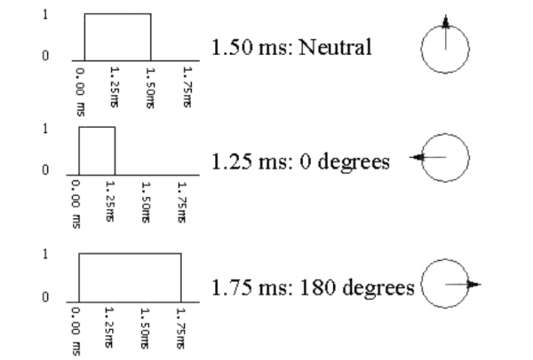
A servo motor possesses a unique characteristic that sets it apart from regular DC motors. Unlike DC motors, it does not allow continuous rotation of its output shaft; instead, it enables rapid and precise movement to specific output angles, usually within a range of 0 to 180 degrees. To achieve this, it requires a precisely pulsed input signal. For a more comprehensive understanding of servo motors, you can find a concise and informative discussion on the topic at the Seattle Robotics Society’s resource:
http://www.seattlerobotics.org/guide/servos.html
Here is their graphical representation, demonstrating the correlation between the input pulse and the rotation angle of the output shaft:
Due to the presence of a gearbox that efficiently transfers power and speed from the motor to the output shaft, servo motors are generally known for their substantial power capabilities. Interestingly, with minor adjustments, a servo can be hacked and repurposed as a cost-effective continuous rotation gearbox motor. For step-by-step guidance on how to perform this modification, you can refer to the tutorial provided by the Seattle Robotics Society:http://www.seattlerobotics.org/guide/servohack.html
Here is a useful link for purchasing affordable DC gearbox motors, which can be a more economical option compared to modifying a servo:http://www.solarbotics.com/motors_accessories/gear_motors/
2a) Perform a test on your servo motor.
Setup the servo and upload the code from the following example:http://arduino.cc/en/Tutorial/Sweep
(2a) Perform a test on your servo motor
Setup the servo and upload the code from the following example:
http://arduino.cc/en/Tutorial/Sweep
Servo motor power requirements
Unlike DC motors, which have varying power requirements, a servo motor typically operates within a voltage range of 4.5 to 6VDC. When powering the servo from a supply with less than +5V, it is essential to insert a 1kOhm resistor between the I/O line and the servo’s control line. If you intend to use the same power supply for both the Arduino and the servo, ensure that it can deliver a current of at least 1000mA. Particularly when controlling multiple servos, an external power supply becomes necessary as servos can be quite demanding in terms of power consumption. In case you are using separate power supplies for the Arduino and the servo, remember to connect their ground (GND) lines together.
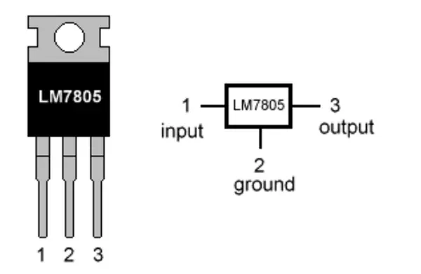
Given that the power supply commonly used in this class provides 9V @ 1000mA, we must devise a method to transform the 9V into 5V to effectively power the servo. To accomplish this task, the 7805 voltage regulator IC comes into play as it serves the purpose of converting the voltage accurately.
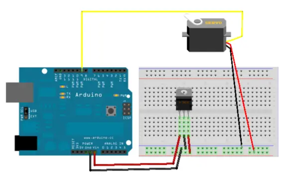
Below is a Fritzing sketch that demonstrates the proper connection of the servo to an Arduino board:
Alternatively, you have the option to utilize the Arduino’s built-in voltage regulator to obtain the 5VDC power required for the servo from the Arduino’s 5V output. However, it is essential to be cautious with larger servos as they can draw more current and potentially cause overheating and damage to the smaller onboard voltage regulator.
2b) Processing to Servo
With the Arduino circuit set up, we can now proceed to control the rotation angle of the servo using a slider in Processing. To enable communication between Processing and Arduino, we will use firmata, and the servo library will handle the servo control on the Arduino board. Simply upload the Servo firmata onto your Arduino board by navigating to Arduino’s menu, then selecting File > Examples > Firmata > Servo Firmata.
After completing the necessary code modifications, proceed to upload the code to your Arduino board.
In Processing type in the following:
import processing.serial.*;
import cc.arduino.*;
import controlP5.*;
ControlP5 controlP5;
Arduino arduino;
int servoAngle = 90;
void setup() {

size(400,400);

println(Arduino.list());
arduino = new Arduino(this, Arduino.list()[0], 57600);

for (int i = 0; i <= 13; i++)
arduino.pinMode(i, Arduino.OUTPUT);

controlP5 = new ControlP5(this);
controlP5.addSlider("servoAngle",0,180,servoAngle,20,10,180,20);

}
void draw() {
arduino.analogWrite(9, servoAngle);
//delay(15);
}
If Processing doesn’t pique your interest for controlling servo movements, but you prefer using only the Arduino and electronic circuitry, this example utilizing the Arduino servo library could be of interest to you.http://arduino.cc/en/Tutorial/Knob
(3) DC motor control – simple
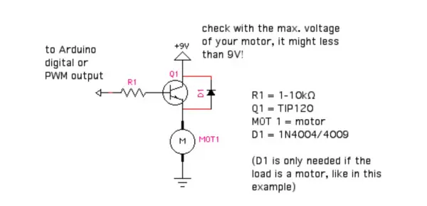
DC motors and servo motors require different control methods. For basic DC motor control, you can use a power transistor like the TIP120, controlled by one of the Arduino’s PWM pins. Because DC motors consume a significant amount of power, it is not advisable to power them directly through the Arduino’s PWM pin. In many instances, an external power supply should be employed with the Arduino to provide the required voltage and current for the motor. This example demonstrates a straightforward approach to control a DC motor, allowing you to adjust its speed but not change its direction of rotation (forward/backward).
Here’s how the circuit setup appears:
In the context of the breadboard, this would appear as follows:
Ensure that your Arduino board is powered using an external power supply with this configuration!
Arduino code for this project: upload the SimpleAnalogFirmata example – File >
Examples > Firmata > SimpleAnalogFirmata
Processing code is implemented to enable motor speed control through a GUI slider:
import processing.serial.*;
import cc.arduino.*;
import controlP5.*;
ControlP5 controlP5;
Arduino arduino;
Winkler, Arduino motor control, p. 6
int DC_speed = 150; // 0-255
void setup() {

size(400,400);

println(Arduino.list());
arduino = new Arduino(this, Arduino.list()[0], 57600);

for (int i = 0; i <= 13; i++)
arduino.pinMode(i, Arduino.OUTPUT);

controlP5 = new ControlP5(this);
controlP5.addSlider("DC_speed",0,255,DC_speed,20,10,255,20);

}
void draw() {
arduino.analogWrite(9, DC_speed);

}
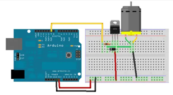
(4) DC motor control – SN754410
Although a bit more intricate, this method offers the advantage of controlling both the direction and speed of the motor. The SN754410 integrated circuit (IC) proves to be practical as it enables you to manage the DC motor’s speed and direction using just one PWM output and two digital outputs from your Arduino board.
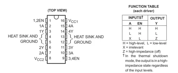
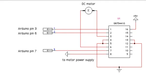
For more comprehensive instructions on employing the SN754410 motor driver IC with a microcontroller, refer to pages 255 to 260 in O’Sullivan and Igoe’s book “Physical Computing.” Additionally, provided below is a circuit diagram illustrating how to interface the SN754410 with the Arduino board.
Furthermore, here is an image depicting how this setup should appear on your breadboard:
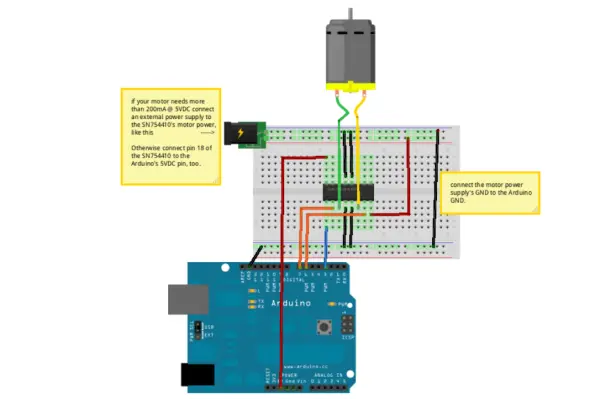
Before proceeding, ensure that you have uploaded the standard Firmata code onto your Arduino board. This will be essential for the processing code to function correctly.
import processing.serial.*;
import cc.arduino.*;
import controlP5.*;
ControlP5 controlP5;
Arduino arduino;
int DC_speed = 150; // 0-255
int direction = 1; // 0: backward, 1: forward
void setup() {

size(400,400);

println(Arduino.list());
arduino = new Arduino(this, Arduino.list()[0], 57600);

for (int i = 0; i <= 13; i++)
arduino.pinMode(i, Arduino.OUTPUT);
// pin3: PWM, pin 6: 1A, pin 7: 2A (see SN754410 datasheet)

controlP5 = new ControlP5(this);
controlP5.addSlider("DC_speed",0,255,DC_speed,20,10,255,20);

Radio r = controlP5.addRadio("radio",20,50);
//r.deactivateAll();
// use deactiveAll to NOT make the first radio button active.
r.add("forward",0);
r.add("backward",1);

}
void draw() {
arduino.analogWrite(3, DC_speed);

if (direction == 1) { // run in one direction, i.e. forward
arduino.digitalWrite(6, 1);
arduino.digitalWrite(7, 0);
}
else { // run in the opposite direction, i.e. backward
arduino.digitalWrite(6, 0);
arduino.digitalWrite(7, 1);
}
}
void radio(int theID) {
switch(theID) {
case(0):
direction = 1; // forward
break;
case(1):
direction = 0; // backward
break;

   }

}
For those intrigued by the kinetic and mechanical aspects of motor output, I recommend reading pages 271 to 283 in O’Sullivan and Igoe’s book “Physical Computing,” where you can find in-depth information on “Basic Mechanics.”
Engaging with LEGO Technic pieces offers an excellent opportunity to explore kinetic systems and Arduino-controlled motors. To get started, I recommend checking out these helpful tutorials: [provide links or resource names here].
http://www.clear.rice.edu/elec201/Book/legos.html
http://sariel.pl/2009/09/gears-tutorial/
http://neuron.eng.wayne.edu/LEGO…/lego_building_tutorial.pdf
- How do I control a servo with Processing and Arduino?
Upload Servo Firmata to Arduino, run Processing with the cc.arduino library, create a slider (servoAngle 0-180) and send values; Processing code uses arduino.analogWrite(9, servoAngle). - What voltage do servos typically require?
Servo motors typically operate within 4.5 to 6VDC. - Can I power a servo from the Arduino 5V pin?
Yes, but be cautious: larger servos may draw enough current to overheat or damage the onboard regulator; an external supply is recommended for multiple or large servos. - How do I power a servo from a 9V class power supply?
Use a 7805 voltage regulator IC to convert 9V to 5V for the servo, or use the Arduino's 5V regulator with caution. - How can I control DC motor speed with Arduino and Processing?
Upload SimpleAnalogFirmata to Arduino, use Processing with a slider (DC_speed 0-255) and call arduino.analogWrite(pin, DC_speed) to set PWM speed. - How do I control DC motor direction and speed?
Use an SN754410 motor driver IC; control speed via one PWM pin and direction via two digital outputs as shown in the Processing example. - Do I need to share grounds when using separate power supplies?
Yes, if using separate power supplies for Arduino and motors/servos, connect their ground lines together. - What resistor should be used when powering a servo from less than 5V?
If powering a servo from under +5V, insert a 1 kOhm resistor between the I/O line and the servo control line. - Which Processing library is used to build the GUI sliders?
The controlP5 library is used to create sliders and radio buttons in Processing. - What Arduino examples are used for testing servos and motors?
Use the Arduino Sweep example to test servos, Servo Firmata for Processing servo control, and SimpleAnalogFirmata for basic DC motor control.