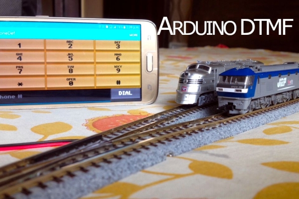
Controlling a model train layout with a wired throttle and turnout controllers might be a good start for beginners but they pose a problem of non-portability. Also, the wireless controllers which come in the market can either control only some locomotives or are a bit too expensive. So, in this instructable, let’s learn how to make a simple wireless model train layout control setup with a smartphone so you can sit back, relax on your couch and have a control on your layout. Let’s get started!
Step 1: Watch the Video!
Step 2: Collect All the Stuff!
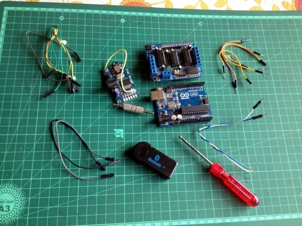
Before starting to build, make sure you have all of the following parts, materials, tools, and supplies:
- An Arduino board, preferably an Arduino UNO, MEGA, Leonardo, or similar ones which can be attached to an Adafruit motor driver shield.
- An Adafruit motor driver shield.
- A 12-volt DC power source.
- A DTMF decoder.
- Wires to connect the track power and turnouts(click on the image to know more).
- Wires to connect the DTMF decoder to digital pins and power(click on the image to know more).
- A smartphone equipped with a DTMF tone generator app.
- A crosshead screwdriver.
- A 1KΩ – 10KΩ resistor.
Step 3: Program the Arduino Board
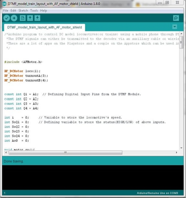
If you don’t have Arduino IDE on your computer, download it from here. The library for the Adafruit motor driver shield can be found here, in case you don’t have it in your IDE. Make sure you install this in your IDE before compiling the program. If you need help installing a library, check this link out.
Step 4: Modify the DTMF Decoder
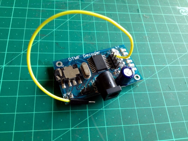
Look for an LED on the board marked as ‘DV’, it lights up whenever the DTMF decoder receives an appropriate audio signal. Trace its path to the chip(make sure you are not following the GND connection) and solder a wire where the copper trace connects the chip’s pin to the resistor connecting to the LED.
Step 5: Make the Layout
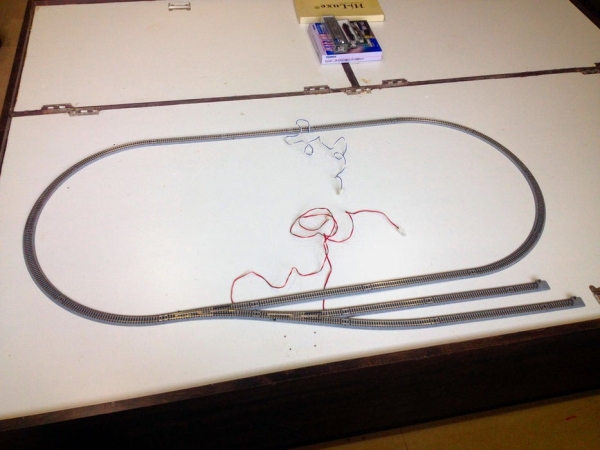
The test layout which I made is made up of a small oval loop along with two yard-sidings.
Step 6: Make All the Wiring Connections
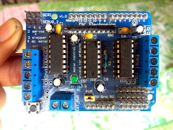
Connect a ‘pull-down’ resistor between the pins GND and A0. Plug the AF motor shield on the Arduino board by carefully aligning the pins of the shield to the sockets on the Arduino board and pushing the shield down to secure it firmly on the Arduino board.
Make the following wiring connections:
- Connect any one of the two turnouts to the screw terminal blocks marked ‘M4’.
- Connect the second turnout to the screw terminal blocks marked ‘M3’.
- Connect the wires of the power feeder track to the screw terminal block marked ‘M1’.
- Connect the digital outputs of the DTMF decoder to the analog inputs of the Arduino board as follows:
- D0 to A1
- D1 to A2
- D2 to A3
- D3 to A4
- DV to A0
Source: Control Your Model Train Layout With Your Mobile Phone!