Summary of Communication between a USB/serial device and an AVR (atmega/Arduino) microcontroller
The article describes a project to interface a USB-to-UART device (CP2103) with an ATmega microcontroller. The user attempted a two-stage conversion: USB to RS232 using an AVR-CDC project on an ATmega328, followed by RS232 to TTL conversion. However, the signal is lost after the first stage, and no output appears at the CDC-232 module's pins.
Parts used in the Project:
- Device with CP2103 USB to UART Bridge Controller
- Windows PC
- ATmega328 microcontroller
- 16MHz crystal oscillator
- CDC-232 circuit board
- RS232 to TTL converter circuit
- Oscilloscope
I have a device which provides a USB port. If I attach it to a Windows PC it is recognized as a “CP2103 USB to UART Bridge Controller”. According to the device documentation, it should communicate in serial format at 38400bps.I have to talk to this device with a atmega microcontroller.
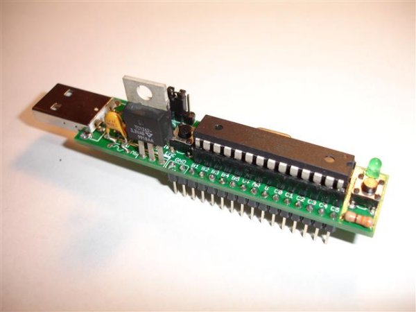 Since the USB pinout is different from the serial UART of the uC, firstly I thought I would need a circuit to convert the signals. I found the AVR-CDC project and put on a CDC-232 in order to convert USB (
GND, D+, D-, VCC) to RS232 (TX, RX, GND):
To make it I used another atmega328 as uC, flashed with the specific hex, with a 16Mhz crystal instead of the 12Mhz one specified into the diagram.
Then I built another piece of circuit to convert the RS232 signal to TTL:
So the signal conversion should be USB -> RS232 -> TTL.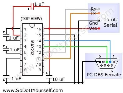 I programmed my uC to send some data to the device and I can follow the signal with the oscilloscope until it enter into the CDC-232, then I lose it. I have no output on pins 4 and 5 of the CDC-232 uC, where I should have a USB signal.
Is my overall approach right? Sould I go on debugging the CDC-232 part or there is something wrong elsewhere?
For more detail: Communication between a USB/serial device and an AVR (atmega/Arduino) microcontroller
- How should the signals be converted between the USB device and the microcontroller?
The proposed approach involves converting signals from USB to RS232 and then from RS232 to TTL. - What microcontroller was used for the CDC-232 conversion?
An ATmega328 microcontroller was used, flashed with specific hex code from the AVR-CDC project. - What modification was made to the crystal frequency in the CDC-232 setup?
A 16MHz crystal was used instead of the 12MHz one specified in the original diagram. - At which point does the signal transmission fail?
The signal can be observed until it enters the CDC-232, but it is lost immediately after that point. - Is there any output on the pins of the CDC-232 unit?
No, there is no output observed on pins 4 and 5 of the CDC-232 where a USB signal should appear. - What is the communication speed specified for the target device?
The device documentation states it communicates in serial format at 38400bps. - Does the USB pinout match the serial UART of the microcontroller?
No, the USB pinout is different from the serial UART of the microcontroller.