
Summary of Combination Circuit for Digital and Analog
This article outlines a project to build an Arduino-based alarm clock. Students learn to program analog signals for music playback, control a four-digit seven-segment display using a 74HC595N shift register, and integrate these components with an LM386 audio amplifier. The goal is to combine digital timing and analog audio into a functional circuit by the second week of the course.
Parts used in the Alarm Clock:
- Arduino Board
- 74HC595N Shift Register
- 4-Digit Seven-Segment Display (Common Anode)
- LM386 Audio Amplifier
- Loudspeakers
- Breadboard
- Capacitors
- Resistors
Goals
-
Understand the Analog Signals and use your knowledge to program your Arduino and let it play music
-
Get known of the Seven-segment display and use your Arduino Board together with the Shift Register to control the number.
-
In the Second Week you will be asked to implement a circuit to combine these first two parts together to build a alarm clock.
Introductions
Shift Register
In digital circuits, a shift register is a cascade of flip flops, sharing the same clock, in which the output of each flip-flop is connected to the “data” input of the next flip-flop in the chain, resulting in a circuit that shifts by one position the “bit array” stored in it, shifting in the data present at its input and shifting out the last bit in the array, at each transition of the clock input.
What we are using is 74HC595N, it has 8-bit serial input and 8-bit serial or parallel output. Below is its function diagram and Pin Diagram:
For more detailed information about thie shift register you can refer to this page: 74hc_hct595.pdf.
7-segment Display
A seven-segment display, or seven-segment indicator, is a form of electronic display device for displaying decimal numerals that is an alternative to the more complex dotmatrix displays. Seven-segment displays are widely used in digital clocks, electronic meters, and other electronic devices for displaying numerical information. Above is how it looks like.
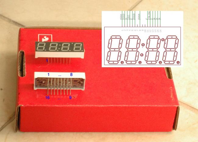
What we will use is a 4 digits Seven segment Display, below is the pin and circuit diagram:
Read the circuit 5 (page 16) on this Document. You will use a similar circuit to turn on the segments of the 7-segment display but instead of using LEDs you will use the segments of the display. Also remember that the 7-segment display is “common anode”, so it will need a 0 to turn on one segment instead of a 1. You will use the 74HC595 Shift Register to provide more outputs to the Arduino. Intially you can only wire DIG1 by connecting pin 1 to +5V.
Here is the datasheet:http://www.sparkfun.com/datasheets/Components/LED/7-Segment/YSD-439AR6B-35.pdf
breadboard layout sheet http://ardx.org/src/circ/CIRC05-sheet-SPAR.pdf lm386.pdf
Audio Amplifier
An audio power amplifier is an electronic amplifier that amplifies low-power audio signals (signals composed primarily of frequencies between 20 – 20 000 Hz, the human range of hearing) to a level suitable for driving loudspeakers and is the final stage in a typical audio playback chain.
While the input signal to an audio power amplifier may measure only a few hundred microwatts, its output may be tens, hundreds, or thousands of watts.
Also we will give the internal and the pin Diagram below to show you how you can connect this Audio amplifier.
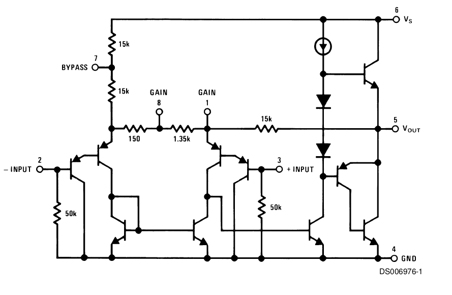
To make the LM386 a more versatile amplifier, two pins (1 and 8) are provided for gain control. With pins 1 and 8 open the 1.35 kΩ resistor sets the gain at 20 (26 dB). If a capacitor is put from pin 1 to 8, bypassing the 1.35 kΩ resistor, the gain will go up to 200 (46 dB). If a resistor is placed in series with the capacitor, the gain can be set to any value from 20 to 200. Gain control can also be done by capacitively coupling a resistor (or FET) from pin 1 to ground.
You can find more specific details about the LM386 Audio Amplifier in this file: lm386.pdf
For more detail: Combination Circuit for Digital and Analog
- How does the 74HC595N shift register work?
It shifts a bit array by one position at each clock transition, taking serial input and providing serial or parallel output. - What type of seven-segment display is used?
A 4-digit common anode display is used, requiring a 0 signal to turn on segments. - Can I adjust the gain of the LM386 amplifier?
Yes, placing a capacitor between pins 1 and 8 increases gain to 200, while leaving them open sets it to 20. - What is the purpose of the audio power amplifier in this project?
It amplifies low-power audio signals to a level suitable for driving loudspeakers. - How do you connect the first digit of the seven-segment display initially?
You wire DIG1 by connecting pin 1 to +5V. - What frequency range does the human hearing cover for this project?
The human range of hearing is between 20 and 20,000 Hz. - What is the main goal of the second week assignment?
To implement a circuit that combines the analog music and digital display parts into an alarm clock. - Does the 74HC595N have parallel outputs?
Yes, it has 8-bit serial input and 8-bit serial or parallel output.
