Summary of Calibrating sensor input using Arduino
This article explains an Arduino technique for calibrating sensor input by recording the highest and lowest readings during the first five seconds of startup. This establishes a dynamic range for subsequent loop operations. The circuit connects an analog sensor to pin 0 and an LED to pin 9, utilizing specific resistors to condition signals.
Parts used in the Sensor Calibration Project:
- Arduino board
- LED
- Analog sensor (photocell)
- 10K ohm resistor
- 220 ohm resistor
- Breadboard
- Hook-up wire
This example demonstrates one techinque for calibrating sensor input. The Arduino takes sensor readings for five seconds during the startup, and tracks the highest and lowest values it gets. These sensor readings during the first five seconds of the sketch execution define the minimum and maximum of expected values for the readings taken during the loop.
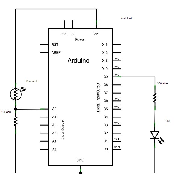
Circuit
Analog sensor (e.g. potentiometer, light sensor) on analog input 2. LED on digital pin 9.
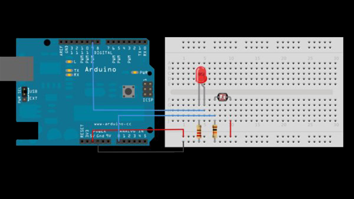
image developed using Fritzing. For more circuit examples, see the Fritzing project page
Connect an LED to digital pin 9 with a 220 ohm current limiting resistor. Connect a photocell to 5V and then to analog pin 0 with a 10K ohm resistor as a reference to ground.
Schematic
Code
Before the setup, you set initial values for the minimum and maximum like so:
int sensorMax = 0; // maximum sensor value
These may seem backwards. Initially, you set the minimum high and read for anything lower than that, saving it as the new minimum. Likewise, you set the maximum low and read for anything higher as the new maximum, like so:
Hardware Required
- Arduino board
- (1) LED
- (1) analog sensor (a photocell will do)
- (1) 10K ohm resistor
- (1) 220 ohm resistor
- breadboard
- hook-up wire
For more detail: Calibrating sensor input using Arduino
- How does the Arduino determine sensor ranges?
The Arduino takes sensor readings for five seconds during startup to track the highest and lowest values. - What pins are used for the components?
The analog sensor connects to analog pin 0 and the LED connects to digital pin 9. - Can I use a potentiometer instead of a photocell?
Yes, the text states an analog sensor such as a potentiometer or light sensor can be used. - Why is the initial minimum set to 1023?
It is set high initially so the code saves any lower reading as the new minimum. - Why is the initial maximum set to 0?
It is set low initially so the code saves any higher reading as the new maximum. - What is the function of the 220 ohm resistor?
The 220 ohm resistor acts as a current limiting resistor for the LED. - What is the function of the 10K ohm resistor?
The 10K ohm resistor serves as a reference to ground for the photocell connection. - When do the calibration readings occur?
Readings are taken during the first five seconds of sketch execution before the main loop begins. - What defines the expected value range?
The highest and lowest values recorded during the first five seconds define the minimum and maximum expected values.