Summary of Bucky Touch: Light-up Dodecahedron Instrument
About two years after building a 120-face LED geodesic dome, the author created the Bucky Touch: a smaller, easier-to-build touch-sensitive dodecahedron instrument with improved capacitive sensors, WS28xx LEDs, MIDI and mono audio outputs, and an Arduino Nano core. The project includes laser-cut MDF and plexiglass parts, a no-glue chassis design, and detailed wiring for LEDs, touch sensors, MIDI, and audio output.
Parts used in the Bucky Touch:
- Two sheets of 16 x 12 0.118 inch MDF
- One sheet of 12 x 12 0.118 inch translucent white plexiglass
- WS2801 or WS2811 pixel LED strip (11 LEDs)
- Arduino Nano
- Prototype board
- ITO Coated PET Plastic 100mm x 200mm
- 11 x 2 MOhm resistors
- 11 x 1 kOhm resistors
- 10k resistor for audio output
- 2 x 0.1 uF capacitors for audio output
- MIDI jack
- Toggle switch
- Push button
- Stereo audio jack
- Header pins
- 2 x M3 nuts
- 2 x M3 x 12 bolts
- Wire wrap wire
- Scotch tape
- Solder
- Electrical tape
- MIDI to USB cable (optional)
About two years ago, I built a big 120 face LED geodesic dome that plays music with a MIDI output. However, it was a difficult build and the sensors weren’t completely reliable. I decided to build the Bucky Touch, a smaller version of my geodesic dome that is easier to construct and has upgraded capacitive touch sensors. The Bucky Touch is designed with both a MIDI and audio output, so you can either use a MIDI device (e.g. a computer or MIDI keyboard) to play the Bucky Touch OR you can directly hook up the Bucky Touch to an amplifier and speaker.

My first prototype in this project was similar, but does not have touch-sensitive faces and instead provides break-out pins that provide access to digitial I/O pins, a TX (transmit) pin, a RX (receive) pin, reset pin, and ground pin. This version I called the Bucky Glow. The pins enable you to connect the Bucky Glow to sensors (e.g. capacitive touch, infrared, ultrasonic), motors, MIDI jacks, and any other electronics you can think of.
This instructable goes through assembly of the Bucky Touch, which is more like a musical instrument in comparison to the Bucky Glow.
Step 1: Supply List
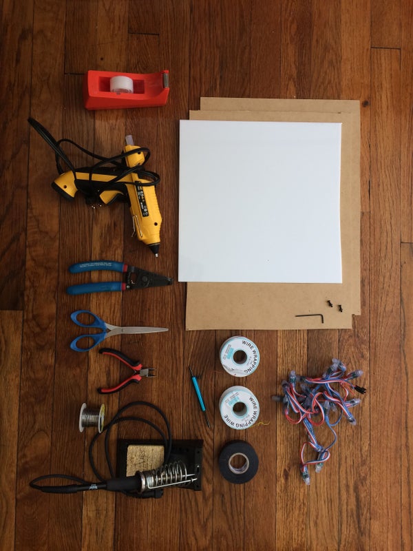
Materials:
1. Two sheets of 16″ x 12″ 0.118″ thick MDF
2. One sheet of 12″ x 12″ 0.118″ thick translucent white plexiglass
3. WS2801 or WS2811 pixel LED strip (11 LEDs): https://www.amazon.com/gp/product/B01AG923GI/ref=o…
4. Arduino Nano: https://store.arduino.cc/usa/arduino-nano
5. Prototype board
6. ITO (Indium Tin Oxide) Coated PET Plastic – 100mm x 200mm https://www.adafruit.com/product/1309
7. 11X 2MOhm resistors
8. 11X 1kOhm resistors
9. 10k resistor for audio output
10. 2X 0.1uF capacitors for audio output
11. MIDI jack:
12. Toggle switch: https://www.digikey.com/product-detail/en/e-switc…
13. Push button: https://www.amazon.com/DAOKI-Miniature-Momentary-…
14. Stereo audio jack: https://www.amazon.com/gp/product/B01MRX7KA1/ref=…
15. Header pins
16. 2X M3 nuts
17. 2X M3x12 bolts
18. Wire wrap wire
19. Scotch tape
20. Solder
21. Electrical tape
22. MIDI to USB cable if you want to play MIDI with computer
Tools:
1. Laser cutter
2. 3D printer
3. Wire cutters
4. Soldering iron
5. Scissors
6. Allen wrench
7. Hot glue gun
8. Wire wrap tool
Step 2: System Overview
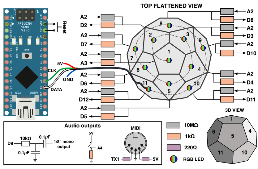
At the heart of the Bucky Touch is an Arduino Nano. The data pin and clock pin of a WS2081 addressable LED strip is connected to pin A0 and A1, respectively. Each face of the dodecahedron has a capacitive touch sensor connected with a 2.2Mohm resistor to the send signal coming from pin A2. The receive pins are A3, D2-D8, and D10-D12. Here is a link to capacitive touch sensors: http://playground.arduino.cc/Main/CapacitiveSensor
The Bucky Touch has both a MIDI output and mono audio signal. Both these signals are discussed in Step 6. The TX pin is used for the MIDI and a PWM signal from pin 9 is used for the audio. To switch between MIDI and mono output, there is a toggle switch connected to pin A3.
The Arduino is programmed to read all the capacitive touch sensors to determine which pentagon key is being pressed by the user. It then outputs signals to update the LEDs and produce a sound, either MIDI or mono audio depending on the direction the toggle switch is flipped.
Step 3: Designing and Cutting the Chassis
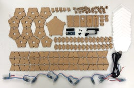
The chassis of the Bucky Touch was designed in Fusion 360. My goal was to design the chassis so it could be assembled without using any glue. The LEDs slide into pentagonal faces, and walls are used to separate the light and provide support for plexiglass above the LEDs. The assembled dodecahedron then attaches to a base that holds the Arduino, jacks, and other electronics. There is a total of 113 MDF parts, and 11 plexiglass parts.
After designing the fully assembled structure, I exported the surface of each part as a DXF file by first starting a sketch on the surface. Then I exited the sketch mode, right-clicked on the new sketch, and then selected “Save as DXF.” See the gif above.
The laser cutter I have accepts PDF files, so I needed a program to import DXF files and arrange the vectors of each part for cutting. I started by using Inkscape, a free vector graphics software. Inkscape works pretty well, but I wanted to find a program more similar to Adobe Illustrator. After some research, I discovered Graphic by Autodesk. Graphic costs a one-time fee of $30 and has similar interface and features to Illustrator, so I think it is a great deal for those searching for cheaper graphic design software without the annual fee. One downside is Graphic can’t import DXF files. So I ended up importing DXF files to Inkscape, and then exporting them as EPS so they could be uploaded to Graphic. It is not the most efficient method, but it tells you how user-friendly I found Graphic to be.The parts were arranged over a 16″x12″ sheet and exported as a pdf for my Epilog Zing laser cutter.
Before cutting all the parts, I tested the fit between joints by cutting a few parts. I wanted the joints to be tight enough so they held together without glue, so it took a lot of cutting and resizing until I was satisfied with the fit. Above are some partly assembled prototypes. I also have all the parts laid out for an older prototype with slightly different parts.
Source: Bucky Touch: Light-up Dodecahedron Instrument
- What microcontroller is used in the Bucky Touch?
The Arduino Nano is the heart of the Bucky Touch. - Which LED strips are compatible with the Bucky Touch?
WS2801 or WS2811 pixel LED strips are used (11 LEDs). - How are the capacitive touch sensors connected?
Each face sensor uses a 2.2 MOhm resistor to the send signal on pin A2, with receive pins on A3, D2–D8, and D10–D12. - Can the Bucky Touch output MIDI and audio?
Yes, it has both a MIDI output (TX pin) and a mono audio output using PWM on pin 9, selectable with a toggle switch on pin A3. - What materials are used for the chassis and faces?
The chassis is laser-cut MDF and translucent white plexiglass, with ITO coated PET plastic for touch faces. - How many MDF and plexiglass parts are there?
The design comprises 113 MDF parts and 11 plexiglass parts. - Is glue required to assemble the chassis?
No, the chassis was designed to be assembled without glue using tight-fitting joints. - What tools are needed to build the Bucky Touch?
Tools include a laser cutter, 3D printer, wire cutters, soldering iron, scissors, Allen wrench, hot glue gun, and wire wrap tool. - How were the laser cut files prepared?
Parts were exported from Fusion 360 as DXF, imported to Inkscape, exported as EPS, then arranged and exported as PDF for the laser cutter. - What was the purpose of the Bucky Glow prototype?
The Bucky Glow exposed breakout pins for digital I/O, TX, RX, reset, and ground to enable external sensors and devices, but lacked touch-sensitive faces.