Summary of Brushless DC (BLDC) motor with Arduino. Part 3 – The Stroboscope Project
Summary (under 100 words): This article describes the hardware build of an Arduino-driven stroboscope using a three-phase BLDC spindle motor salvaged from Xbox 360 DVD drives. It covers donor motor advantages, frame and LED mounting, a detachable motor/LED assembly, and the Arduino-based circuit implemented on a Breadboard Development Shield. Added controls include an RPM potentiometer, direction button with indicator LED, and use of the fourth driver channel (SN754410) to drive the flash LED. Power jumper options (JP1/JP2) to reduce driver heating are also explained.
Parts used in the Arduino Stroboscope Project:
- Xbox 360 DVD-RW drive (donor for three-phase BLDC spindle motor and frame)
- Arduino (MCU)
- Arduino Breadboard Development Shield (sans breadboard)
- SN754410NE quadruple half-H driver IC
- Flash LED
- RPM control potentiometer
- Direction control push button
- Indicator LED for direction
- Connector between Arduino shield and motor frame (optional)
- Diode D1 (used to drop supply voltage)
- Sheet aluminum bracket for LED mounting
- Wires and jumpers JP1 and JP2
- Power supply (5V logic supply and motor supply options)
It has been all dry theory in the Brushless DC (BLDC) motor with Arduino series up to this point. This is where it gets to be more fun. If you’ve just arrived, please check out the previous two installments:
- Driving a three-phase brushless DC motor with Arduino – Part 1. Theory
- Brushless DC (BLDC) motor with Arduino – Part 2. Circuit and Software
 In this final part of the trilogy I am describing the hardware part of the stroboscope project and the making of the zoetrope animations themselves, in hopes that my visitors can take this further and come up with their own animations, which I would absolutely love to see. More details below!
As far as DIY user-friendliness, Xbox 360 DVD BLDC motors stand above the rest
During my search for a perfect donor DVD-RW drive for a (still coming) miniature laser cutter project, I came into possession of some insane amount of broken CD,DVD and Bluray drives and at some point I came across a bunch of broken Xbox 360 drives for sale on eBay that piqued my interest. Once I got them I realized that their main feature is not so much the laser sled positioning mechanism which I was after but rather the three phase BLDC spindle motor that rather basic design which is very compatible with DIY process – no ribbon cables were used. All three windings are conveniently traced to the outside PCB that’s easily solderable. I would have to say that at least one of the Xbox drives I’ve looked into did have a ribbon cable but the ribbon cable ends were not too close together and rather easily solderable themselves. So, if you are interested in this project or just generally in playing with small BLDC motors, definitely do look up broken Xbox drives – they are plentiful and very cheap.
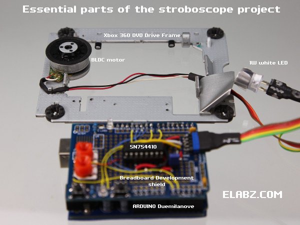
Essential parts of the Arduino Stroboscope project
The Xbox 360 DVD drive has donated another important part of the project – the frame which holds both the spindle drive and the LED. It already had the mounting holes for the BLDC motor and devising a bracket to hold the LED was just a matter of bending some sheet aluminum left over from another DVD drive teardown.
I opted to have the business end of the stroboscope – the motor and the LED – to be detachable from the Arduino “brains” because I wanted to do a lot of testing and playing with other motors using the same electronics. But if you’re making it a stationary device, the connector between the Arduino Development Shield and the motor frame is completely optional. Additionally, I imagine that with a bit of tweaking the Arduino stack can actually be mounted to the underside of the motor frame (which will have to be raised on some sort of standoffs) to make the entire device even smaller.
Arduino Stroboscope Circuit Diagram
The circuit itself was built on an Arduino Breadboard Development Shield, sans the breadboard. I like the flexibility of the Development Shield even though this circuit could have been implemented using the Motor control shield instead. By the way, I have a feeling that Arduino Breadboard Development Shield no longer refers to a particular PCB because there are at least a couple of different ones out there that I saw. But any kind will do for this project – very limited space is actually needed, just one 16-pin IC, a 5-pin connector, a button and an LED (normally a part of any development shield) and a space for a potentiometer. Please note: even though the photo shows two orange pots on the left of the shield, I ended up using only one to control the rotational speed of the zoetrope animation. The second pot was supposed to control the duration of the flash but I’ve since found that the said duration can only be within a very narrow range (2 to 4ms or 1/500 to 1/250 for you photography enthusiasts out there) and I simply set it with a constant in the code instead. Being able to control the flash duration in real time did not seem to add much to the project.
Only a few more components were added to the circuit diagram from the Part 2 of this series of posts, the one that describes the circuit and the software for controlling the BLDC motor. The added parts are the MCU itself (Arduino) and a few controls – the RPM control pot and the direction control button (with the LED to show the direction). The fourth quarter of the QUADRUPLE Half-H Driver SN754410, unused in the previous circuit, is now used to drive the flash LED.
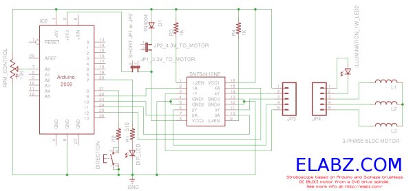 One part of the new scheme that requires some further explanation is the jumpers JP1 and JP2. I have found that the SN754410NE driver gets pretty hot if the stroboscope is left on for a long time. The resistivity of the windings is only 4.3Ω measured across two windings in series (the only way to measure without access to the center point) which means that if we feed the motor control part of SN754410 with the same supply voltage as its logic part +5V, we have more than 1A flowing through it at any given moment, which is higher than what the IC was deigned for. So, I’ve tried two ways of lowering the load supply voltage: lower it some 0.7V by first passing it through the D1 diode (short JP2, open JP1) or take the 3.3V output from Arduino (short JP1, open JP2).
For more detail: Brushless DC (BLDC) motor with Arduino. Part 3 – The Stroboscope Project
- What donor device is recommended for the BLDC motor?
The article recommends Xbox 360 DVD drives because their three-phase BLDC spindle motors have easily accessible winding traces and are cheap and plentiful. - Can the motor and LED assembly be detachable from the Arduino?
Yes, the author made the motor and LED detachable so the same electronics can be used for testing other motors. - What board was the circuit built on?
The circuit was built on an Arduino Breadboard Development Shield without the breadboard. - Which IC is used to drive the motor and the flash LED?
The SN754410NE quadruple half-H driver IC is used, with its fourth channel driving the flash LED. - Is a second potentiometer required to control flash duration?
No, the author used only one potentiometer for RPM and set flash duration as a constant in the code because its usable range is narrow. - Why are jumpers JP1 and JP2 used?
JP1 and JP2 allow lowering the motor driver supply voltage to reduce heating of the SN754410NE either by routing through diode D1 or using the Arduino 3.3V output. - Does the Xbox 360 drive frame help with mounting?
Yes, the DVD drive frame already has mounting holes for the spindle motor and was used to mount the LED bracket. - Can the Arduino stack be mounted to the motor frame?
Yes, the author suggests the Arduino stack could be mounted under the motor frame on standoffs to make the device smaller.