In this tutorial you learn how to make a blinking clock with a difference!
Updated 18/03/2013
Followers of my website would realise that I tend to make too many clocks in those tutorials. Well, I like making clocks… so here is another one. However this time I have tried to make the most simple version possible. Usually projects will have many LEDs, or perhaps an LCD, buzzers, buttons, all sorts of things. Which looks great and will impress many. But the other day I thought to myself … “how few things do you need to show the time?”
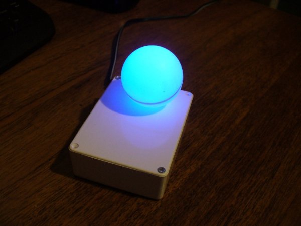
So here is my answer to that question: Blinky the one-eyed clock …
It reminds me of the giant killer orb from The Prisoner… Using a minimal Arduinobootloader system, a DS1307 real time clock IC and an RGB diffused LED … we can make a clock that blinks the time, using the colours of the LED to note different numerical values. For example, if the time is 12:45, the clock will blink red 12 times, then show blue for a second (think of this as the colon on a digital clock) then blink four times in green (for forty minutes), then blink three times in red for the individual minutes. If there is a zero, blink blue quickly. Then the clock will not display anything for around forty seconds, then repeat the process. Here he (she, it?) is blinking the time:
Setting the clock is simple. It is set to start at 12:00 upon power up. So for the first use you have to wait until about five seconds before midday or midnight, then power it up. To save cost it doesn’t use a backup lithium battery on the real-time clock IC, but you could if you really wanted to. If you would like to follow my design process narrative, please read on. If you only want the sketch and schematic, ![]() head to the bottom of this article.
head to the bottom of this article.
Design process narrative…
So let’s get started!
The first thing to do was test the RGB LED for brightness levels, so I just connected it to the digital output pins of my Eleven via suitable current-limiting resistors. Each LED is going to be different, so to ensure maximum brightness without causing any damage you need to calculate the appropriate resistor values. This is quite easy, the formula is: resistor (ohms) = voltage drop / LED current So if you have a 5 V supply, and LED that needs only 2 volts, and draws 20 milliamps (0.2 amps) , the calculation will be: resistor = (5-2)/0.02 = 150 ohms. To be safe I used a 180 ohm resistor. The LED was tested with this simple sketch:
/*
  blinky LED test
 */

int red = 2;
int green = 3;
int blue = 4;
int d = 300;
void setup()
{
  pinMode(red, OUTPUT);
  pinMode(green, OUTPUT);
  pinMode(blue, OUTPUT);
}

void loop()
{
  digitalWrite(red, HIGH);
  delay(d);
  digitalWrite(red, LOW);
  delay(d);
  digitalWrite(green, HIGH);
  delay(d);
  digitalWrite(green, LOW);
  delay(d);
  digitalWrite(blue, HIGH);
  delay(d);
  digitalWrite(blue, LOW);
  delay(d);
}
It was interesting to alter the value of d, the delay variable, to get an idea for an appropriate blinking speed. Originally the plan was to have the LED in a photo frame, but it was decided to mount a ping-pong ball over the LED for a retro-style look. Here is a short video of the result of the test:
If you are going to use a ping-pong ball, please be careful when cutting into it with a knife, initially it may require a lot of force, but once the knife cuts through it does so very quickly.
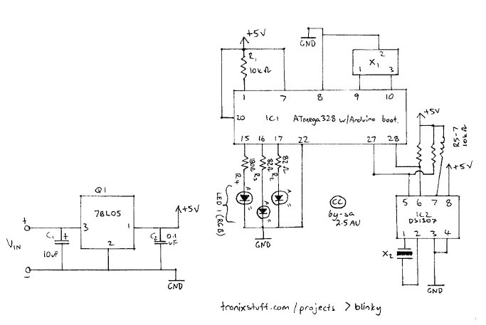
Now it was time to develop the sketch to convert time into blinks. The sketch itself is quite simple. Read the hours and minutes from the DS1307 timer IC; convert the hours to 12 hour time; then blink an LED for the number of hours, display another colour for the colon; divide the minutes by ten and blink that in another colour; then the modulus of minutes and ten to find the individual minutes, and blink those out. Here is the first sketch I came up with. Finally, the code was tested using the Eleven board and my DS1307 real time clock shield. It is best to use existing hardware while testing, before committing to purchasing new hardware and so on. So here it is on the breadboard:
[box color=”#985D00″ bg=”#FFF8CB” font=”verdana” fontsize=”14 ” radius=”20 ” border=”#985D12″ float=”right” head=”Major Components in Project” headbg=”#FFEB70″ headcolor=”#985D00″]Arduino[/box]
For more detail: Blinky the one-eyed clock using Arduino