Assembly instructions for an add-on board for the Arduino.
**** FOR INSTRUCTIONS FOR MARCH 2013, KICKSTARTER PROJECT GO HERE
http://www.instructables.com/id/Blinky-Fish-Kickstarter-Project/ ************
It has some LED’s and a button.
It connects to digital pins 9-13 and ground. My hope is that this will be useful to people that want to play with writing code for the Arduino, but don’t want to build a little circuit every time they want to test something out.

I’m including all the files you would need to build your own. I am also offering these for sale. I figure this is the only real way to find out if this is useful to other people.
I have only a few boards right now, but they are not quite right. I have included a hack towards the end of this instructable.
Here is a small web-store I’ve set-up. The name is stupid, but easy to remember and spell.
www.PoopDirect.com
THIS IS NOW WAS ON KICKSTARTER — ENDS FUNDED MARCH 4, 2013 — BLINKY FISH
Step 1: Parts
Here are the parts!
-PCB –
-3 – LED’s
-Resistors
-Push button
-Right angle header
Step 2: Tools
Tools –
-Solder
-Soldering iron
-Cutters (?)
-The soldering is pretty easy, so I never had to use the flux pen.
– To make anything happen, you will also need an Arduiono 2009 and a computer with the Arduino IDE.
– I like to work on a white peice of paper, it keeps me from loosing parts. It is also a good if you are taking photos.
Step 3: Build – Resistors
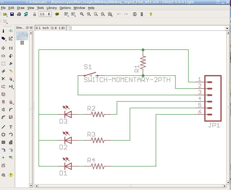
Resistors R2,R3, and R4 are all 330ohm resistors. (orange, orange, brown).
R1 is 1K (brown, black, red).
[NOTE: the resistors shown in the picture are the wrong values – sorry about that, I was distracted by taking the pictures.]
Through hole components are pretty easy to solder.
Here are the steps:
-Find the right resistor
-Put the leads in the holes
-Bend the leads out so the part doesn’t fall out
-Flip the board over
-If the resistor falls out, but it back in
-Turn the soldering iron on and wait for it to warm up
-Put the soldering iron at the joint (between the lead and the silver circle)
-Wait a little bit
-Then touch the solder to the other side of the joint (away from the solder)
-Wait for the solder to melt and go all around the circle
-That is it!
If it doesn’t work (the resistor falls right out or something), then you can just do it again.
After you do the soldering, you just need to clip the leads off. Diagonal cutters are best, but you can use nail clippers or scissors, or whatever.
Step 4: Build – LED’s
Now put on the LED’s
LED’s are one way, the short lead is negative. This side of the LED is usually flat or notched or something like that. On the PCB the flat side of the circle is for the negative lead.
The soldering is the same.
[box color=”#985D00″ bg=”#FFF8CB” font=”verdana” fontsize=”14 ” radius=”20 ” border=”#985D12″ float=”right” head=”Major Components in Project” headbg=”#FFEB70″ headcolor=”#985D00″]-PCB –
-3 – LED’s
-Resistors[/box]
For more detail: Blinky Fish using an Arduino