Greetings everybody!
We hope you are in good health.
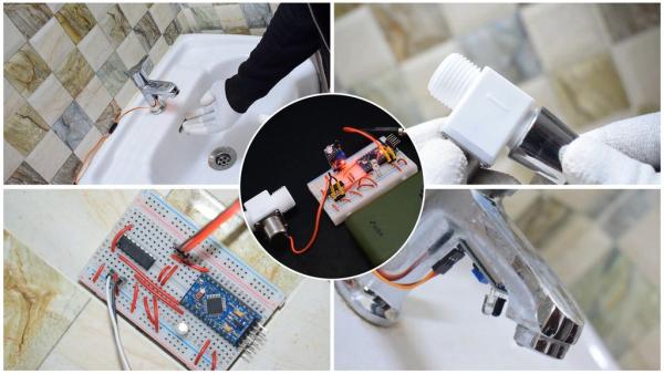
In this Instructable, we will be converting a manual water tap into an automatic one using an Arduino.
We will use an Infrared sensor to detect the presence of a human hand and a solenoid valve to control the flow of water through the tap.
We urge everybody familiar with the field and in possession of the required components to implement this system in your homes to help flatten the curve.
A video tutorial available on YouTube can be found at the end of this instructable. Feel free to watch it! 😀
DISCLAIMER: WE WASTED NO WATER IN THE TESTING OF THIS PROJECT AND RESPONSIBLY REUSED IT.
DIGITAL PREREQUISITE:
1) ARDUINO IDE: Download here.
2) FTDI DRIVERS IF USING THE ARDUINO PRO MINI: Download here.
3) TINKERCAD: Join here.
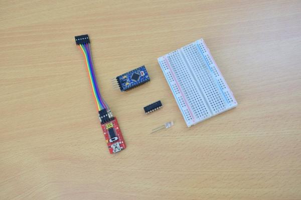
Step 1: HARDWARE REQUIRED
INDIA EXCLUSIVE LINKS:
1) Arduino ProMini: Buy here.
2) FT232RL: Buy here.
3) Half-sized breadboard: Buy here.
4) Dupont jumper wires: Buy here.
5) USB type A to mini B cable: Buy here.
6) L293D motor driver IC: Buy here.
7) 3.6-6V DC bistable solenoid valve: Buy here.
8) Infrared sensor module: Buy here.
9) LEDs: Buy here.
10) 9V cell: Buy here.
11) 9V cell clip connectors: Buy here.
12) 5.5mm DC barrel jacks: Buy here.
13) 5.5mm DC barrel plugs: Buy here.
14) 1/2 inch elbow threaded coupler(female): Buy here.
15) Teflon tape: Buy here.
16) Adjustable wrench: Buy here.
GLOBAL LINKS:
1) Arduino ProMini, FT232RL, Female jumper wires, and USB cable: Buy here.
2) Half-sized breadboard: Buy here.
3) Jumper wires: Buy here.
4) L293D motor driver IC: Buy here.
5) Infrared sensor module: Buy here.
6) DC solenoid valve: Pardon us, we couldn’t find one. Please leave a comment if you know where to get one!
7) 9V cell: Buy here.
8) 9V cell clip connectors: Buy here.
9) DC 5.5mm connectors: Buy here.
10) 1/2 inch elbow threaded coupler(female): Buy here.
11) Teflon tape: Buy here.
12) Adjustable wrench: Buy here.
Step 2: INTRODUCTION
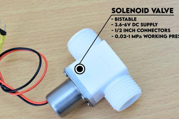
SOLENOID VALVE:
A solenoid valve is an electromechanical device used to control the flow of a fluid through it by energizing an electromagnet which in turn moves the plunger to either restrict or allow the flow of fluid through the valve.
A bi-stable solenoid valve has the ability to “remember” its state even after the power/signal is cut off. For example, a bi-stable solenoid valve will remain closed after receiving a positive/negative pulse depending on the construction, even after the signal is no longer sent. This helps in keeping the power consumption and the temperature rise of the coil to the very minimum.
IR SENSOR:
An IR sensor works on the fundamental principle of emitting and receiving infrared radiation.
The LED emits IR radiation which is detected by the receiver when an object reflects the radiation.
The potentiometer can be used to adjust the sensitivity of the sensor.
L293D MOTOR DRIVER IC:
An individual I/O pin on an Arduino ProMini can supply a maximum current of 40 milliAmperes.
The solenoid valve under test draws approximately 500 milliAmperes during its operation, so we will use an L293D motor driver IC which can supply up to 1.2 Amperes peak and 600 milliAmperes continuously.
The IC can operate off an Arduino Pro Mini’s 5V output and can be used to control a load of up to 36V!
Step 3: PROTOTYPING
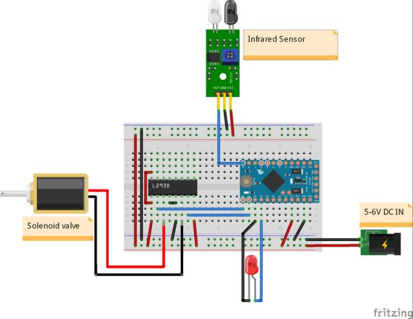
Let’s first hook up the circuit on a breadboard and strike off “proof of concept” from our checklist. 😀
STATUS INDICATOR LED’S POSITIVE TERMINAL -> Digital pin 13 on the Arduino
STATUS INDICATOR LED’s NEGATIVE TERMINAL -> Digital pin 12 on the Arduino
L293D’s pin 1 and 16 -> Arduino’s VCC
L293D’s pin 2 -> Digital pin 10 on the Arduino
L293D’s pin 7 -> Digital pin 11 on the Arduino
L293D’s pin 4 and 5 -> Arduino’s GND
L293D’s pin 8 -> External power supply
SOLENOID VALVE’S TERMINAL “A” -> PIN 4 on the IC
SOLENOID VALVE’S TERMINAL “B” -> PIN 6 on the IC
IR SENSOR’s GND -> Arduino’s GND
IR SENSOR’s VCC -> Arduino’s VCC
IR SENSOR’s OUT -> Digital pin 9 on the Arduino
Step 4: PROGRAMMING
1) Please find the attached, and download it.
2) Open it using the Arduino IDE and verify the same.
3) Select your communication port and board.
4) Upload the code.
Step 5: TESTING THE SYSTEM
1) Disconnect the Arduino from your computer.
2) Use your external power supply to power up the entire system.
3) Bring an object in the IR sensor’s vicinity and check if the status indicator LED lights up and the solenoid valve opens.
4) Displace the object from the sensor’s vicinity and check if the status indicator LED turns off and the solenoid valve closes after 2* seconds.
TROUBLESHOOTING:
1) Status indicator LED doesn’t function:
> Check if the connections are right.
> Check if the LED is healthy.
> Check if the digital pin 12 is set to LOW in the void setup section of the code. (If using an Arduino ProMini)
2) Solenoid valve doesn’t function:
> Check if the connections between the motor driver IC and the Arduino and the solenoid are right.
> Check if the solenoid valve is healthy by externally exciting it.
> Check if the IC is healthy.
> Ensure the external power supply is adequate.
3) IR sensor doesn’t function:
> Check the connections.
> Adjust the on-board potentiometer to adjust the sensitivity.
4) Both the LED and solenoid don’t work:
> Check if the IR sensor functions properly.
*Indicates user-defined values. Feel free to alter it according to your needs.
Step 6: TINKERCARD SIMULATION
1) Visit TINKERCAD and start with a circuit.
2) Import the required components.
3) Make the connections as shown in the wiring diagram.
4) Download the attached text file and copy the code and paste it into the code section of the simulator.
5) Start the simulation.
Since we don’t have an FC-51 IR sensor module in the parts library as of now, we will use a pushbutton to depict the working of the sensor.
Similarly, since we don’t have a solenoid valve, we will use a DC motor to depict its working.
Pushing down on the button will return HIGH and the solenoid valve will open (shown by the motor rotating in a clockwise) direction and the status indicator LED starts glowing.
Letting go of the pushbutton will return LOW and the solenoid valve will close (shown by the motor rotating in the anti-clockwise direction) and the status indicator LED will turn off.
Step 7: PLUMBING
1) Turn off the main water outlet valve at your sink.
2) Disconnect the pipe and open the water tap to drain all the fluid in the system.
3) Connect a 1/2″ female coupling or a repurposed hose to the main valve.
4) Connect the other end of the coupling to the inlet of the solenoid valve.
5) Connect the water tap’s pipe to the outlet of the solenoid valve.
6) Open the solenoid valve by externally powering it and check if the water flow through the system is effective.
7) Close the solenoid valve and check if the water stops flowing through the tap.
TROUBLESHOOTING:
1) Water leakage:
> Check the tightness of the connections.
> Use Teflon tapes wherever possible to avoid leakage.
2) Low discharge:
> Check if the water inlet and outlet are properly connected with respect to the solenoid valve’s construction.
> Avoid bends and twists in the pipes.
> Clean the aerator.
Step 8: MOUNTING
1) Stick the IR sensor to the underside of the water tap.
2) Stick the CPU to the wall.
3) Plug in the IR sensor’s cables.
4) Plug in the solenoid valve’s cables.
5) Stick the 9V cell close to the CPU and connect the power cables.
Source: AUTOMATIC WATER TAP