Summary of ATtiny85 POV Display using arduino
This article guides readers through building a low-cost ($5) Persistence of Vision (POV) display using a DC motor and an ATtiny85 microcontroller. Unlike previous attempts with oscillating shafts, this design uses a spinning motor to create visual illusions by rapidly toggling LEDs. The project involves creating a rotating LED bar, programming the chip via Arduino, and assembling the components into an enclosure.
Parts used in the ATtiny85 POV Display:
- 5 LEDs
- 3V Coin Cell
- Coin Cell Holder
- USB Header
- ATtiny85 Microcontroller
- DC Motor
- Case/Enclosure
- Piece of wood or cardboard
- IC holder
- Protoboard
- Jumper Cables
- Arduino Duemilanove/Uno/Mega
- 10 Micro farad Capacitor
- USB cable for the Arduino
- Breadboard
The first time I saw a POV (Persistence Of Vision) display was on a show called FAQ on TV. The POV display consisted of an oscillating shaft with 6 LED’s mounted on the end of the shaft.
Since then I have always wanted to make one myself, I tried making one about 2 months ago with an oscillating shaft myself but I was not successful as the speed of the shaft was too low for the POV display to work. Now I decided to make the POV display with just a DC Motor instead of an oscillating shaft as they are much cheaper and easily available compared to the shafts.
In this instructable I will show you how to make the POV Display yourself!
This is a very simple project both on hardware and software (coding) areas. It costed me only about 5$ to make it from start to finish!
So lets get started!
Here is a video of it in action!
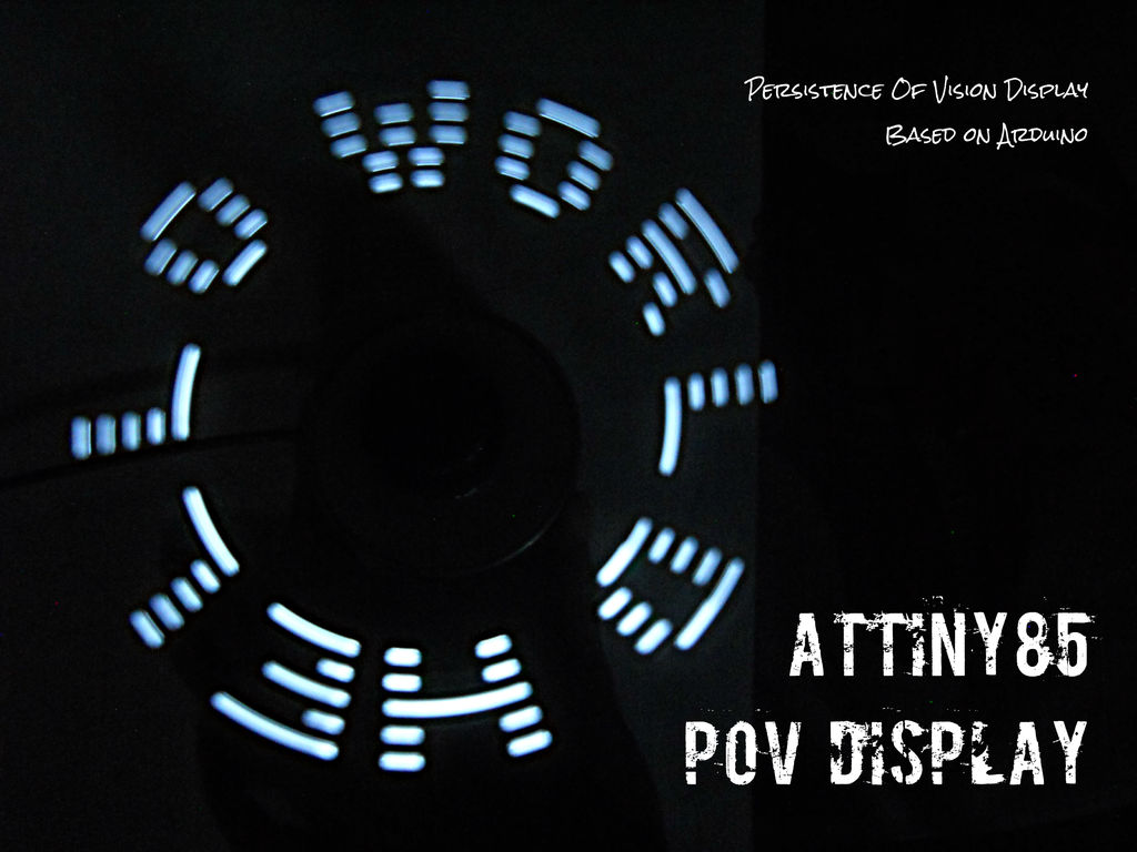
Note: The brightening and dimming of the LEDs in the video is due to my crappy camera, in reality its consistent and quite bright.
Step 1: Persistence Of Vision and how it works
POV stands for Persistence Of VIsion.
Persistence Of Vision is the phenomenon of the eye by which an image seen by our eye persists for about 0.04s during which any other images that we see are merged together with this image.
This phenomenon is used in the POV Display as we turn the LEDs on and off in such a way that the different images overlap each other forming letters.
For example:
The formation of the letter E with 5 LEDs;
1 2 3 <- Time
1 1 1 <- Bulb 1
1 0 0 <- Bulb 2
1 1 1 <- Bulb 3
1 0 0 <- Bulb 4
1 1 1 <- Bulb 5
Each column represents the 5 LEDs we used to make the display. Each element in the row represents the state of the LED at that given time.
So at t = 1 Bulb 1,2,3,4,5 are all on
at t=2,3 Bulb 1,3,5 are on
This way we can visually see the letter E formed by the LEDs but the time interval would be very small in milliseconds and not as given in the example.
Due to the short time intervals and the ability of the LEDs to turn on and off very quickly we can see the letter E as all the 3 images merge. As the motor is spinning, as time passes the LEDs move from one position to the next so all these images are merged together.
For more information on how this works have a look at these links:
- http://www.vision.org/visionmedia/article.aspx?id=…
- http://en.wikipedia.org/wiki/Persistence_of_vision
Note: You can see in the above images how the 3 different pictures merge to form the letter E
Here is an animated gif that shows the formation of the letter E :http://www.instructables.com/files/orig/FIZ/ZDS5/HW4OQXU8/FIZZDS5HW4OQXU8.gif
Step 2: Materials and Tools required
Materials :
1) 5 LEDs (Radioshack) (Ebay)
2) 3V Coin Cell (Radioshack)(Ebay)
3) Coin Cell Holder (Radioshack)(Ebay)
4) USB Header (a normal USB cord would do)
5) ATtiny85 (Ebay)(Atmel Sample)
6) DC Motor (Radioshack)(Ebay)
7) A Case/ Enclosure to keep the motor in
8) A piece of wood or cardboard for the LED bar
9) IC holder (Ebay)
10) Protoboard (Radioshack)(Ebay)
11) Jumper Cables (Radioshack)(Ebay)
Materials for Programming the ATtiny85 chip :
1) Arduino Duemilanove/Uno/Mega
2) 10 Micro farad Capacitor (Radioshack)
3) USB cable for the Arduino
4) Breadboard (Radioshack)(Ebay)
Tools :
1) Glue Gun
2) Soldering Iron
3) Leatherman tool (Optional)
4) Scissors
Note: Buying the materials from ebay would be cheaper but the quality would be just as bad, whereas radioshack is a bit more expensive but its worth it all for the great quality.
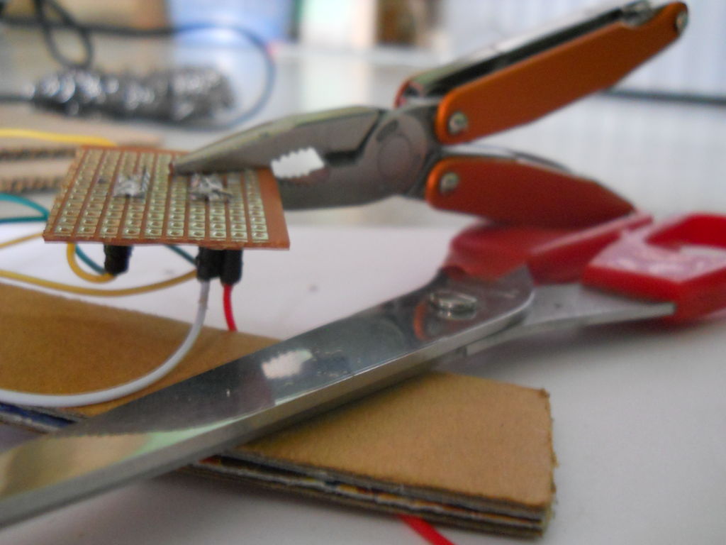
Step 3: Making the LED bar
Cut out a piece of cardboard/wood in which you can mount 5 LEDs and attach it to the motor, this would be the rotating bar of the POV.
Make 5 holes in the cardboard one next to the other in which the LEDs will fit in snug. Insert the LEDs and connect all the cathodes (-) together forming a common cathode leaving the anodes separately.
Note : Diffused LEDs give the best results so its a good idea to diffuse the LEDs. You can do this by sanding the LEDs with sandpaper.
Add a coin or some sort of counter weight on the other end of the LED bar for perfect rotation when the motor is added.
For more detail: ATtiny85 POV Display using arduino
- How does a POV display work?
It uses the eye's persistence of vision where images persist for 0.04s, merging rapidly on/off LED states into letters as the motor spins. - What is the best way to diffuse the LEDs?
Sanding the LEDs with sandpaper is recommended to achieve diffused light for the best results. - Can I use an oscillating shaft instead of a DC motor?
The author previously tried an oscillating shaft but failed because the speed was too low; a DC motor is preferred for being cheaper and faster. - What is the total cost to build this project?
The project cost approximately $5 from start to finish. - Does the video show consistent LED brightness?
No, the brightening and dimming seen in the video is due to the camera; in reality, the brightness is consistent. - How should the LEDs be connected on the bar?
All cathodes (-) should be connected together to form a common cathode while leaving the anodes separate. - Why is a counter weight needed?
A coin or counter weight is added to the opposite end of the LED bar to ensure perfect rotation when the motor is attached. - Which microcontroller is used for this project?
An ATtiny85 microcontroller is used to control the LEDs.