I apologize if you find spelling errors or nonsensical text, my language is Spanish and has not been easy to translate, I will improve my English to continue composing instructables.
In today’s technology, especially electronics have come a long way, to the point that today can make projects a few years ago were very complicated to implement, thanks to these technological advances are now able to design and implement our houses projects.
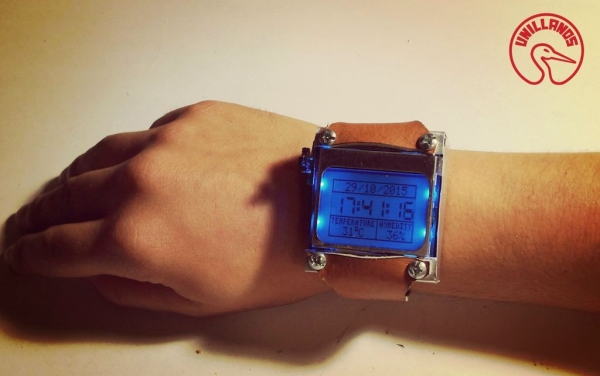
and through this article I come to show you my new project, which consists of a wristwatch, so I called Arduino Watch Sport.
Step 1: Vídeo !
Step 2: Materials !
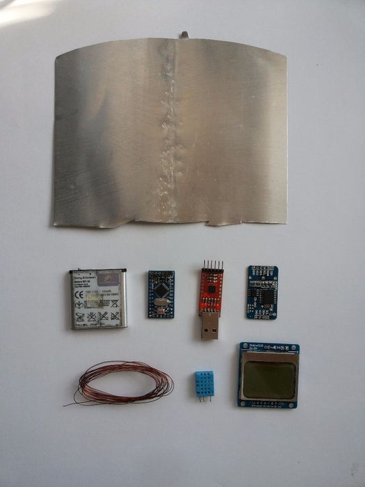
List:
- Sheet from Aluminum
- Battery 3.7V – 930mA
- Arduino Mini Pro 5V – 16MHz
- Converter RS232
- Module Clock RTC DS3231
- Wire from copper
- Module from Temperature – Humedity
- LCD Nokia 5110
- Leather 20X20cm
- Screws X4
- Switch
Step 3: Arduino Pro Mini

Overview
The Arduino Pro Mini is a microcontroller board based on the ATmega328 (datasheet). It has 14 digital input/output pins (of which 6 can be used as PWM outputs), 6 analog inputs, an on-board resonator, a reset button, and holes for mounting pin headers. A six pin header can be connected to an FTDI cable or Sparkfun breakout board to provide USB power and communication to the board.
The Arduino Pro Mini is intended for semi-permanent installation in objects or exhibitions. The board comes without pre-mounted headers, allowing the use of various types of connectors or direct soldering of wires. The pin layout is compatible with the Arduino Mini. There are two version of the Pro Mini.
One runs at 3.3V and 8 MHz, the other at 5V and 16 MHz.
Summary
Microcontroller……………….ATmega328
Operating Voltage………….3.3V or 5V (depending on model)
Input Voltage…………………3.35 -12 V (3.3V model) or 5 – 12 V (5V model)
Digital I/O Pins………………14 (of which 6 provide PWM output)
Analog Input Pins…………..6
DC Current per I/O…………Pin 40 mA
Flash Memory………………..32 kB (of which 0.5 kB used by bootloader)
SRAM …………………………..2 kB
EEPROM………………………1 kB
Clock Speed…………………..8 MHz (3.3V model) or 16 MHz (5V model)
Input and Output
Each of the 14 digital pins on the Pro Mini can be used as an input or output, using pinMode(), digitalWrite(), anddigitalRead() functions. They operate at 3.3 or 5 volts (depending on the model). Each pin can provide or receive a maximum of 40 mA and has an internal pull-up resistor (disconnected by default) of 20-50 kOhms. In addition, some pins have specialized functions:
- Serial: 0 (RX) and 1 (TX). Used to receive (RX) and transmit (TX) TTL serial data. These pins are connected to the TX-0 and RX-1 pins of the six pin header.
- External Interrupts: 2 and 3. These pins can be configured to trigger an interrupt on a low value, a rising or falling edge, or a change in value. See the attachInterrupt() function for details.
- PWM: 3, 5, 6, 9, 10, and 11. Provide 8-bit PWM output with the analogWrite() function.
- SPI: 10 (SS), 11 (MOSI), 12 (MISO), 13 (SCK). These pins support SPI communication, which, although provided by the underlying hardware, is not currently included in the Arduino language.
- LED: 13. There is a built-in LED connected to digital pin 13. When the pin is HIGH value, the LED is on, when the pin is LOW, it’s off.
The Pro Mini has 8 analog inputs, each of which provide 10 bits of resolution (i.e. 1024 different values). Four of them are on the headers on the edge of the board; two (inputs 4 and 5) on holes in the interior of the board. The analog inputs measure from ground to VCC. Additionally, some pins have specialized functionality: I2C: A4 (SDA) and A5 (SCL). Support I2C (TWI) communication using the Wire library.There is another pin on the board: Reset. Bring this line LOW to reset the microcontroller. Typically used to add a reset button to shields which block the one on the board.
- I2C: A4 (SDA) and A5 (SCL). Support I2C (TWI) communication using the Wire library.There is another pin on the board:
- Reset. Bring this line LOW to reset the microcontroller. Typically used to add a reset button to shields which block the one on the board.
Read more: Arduino Watch Sport