Summary of Arduino Tutorial – Chapter 2.3: Schematic and Breadboard Diagrams
This article introduces schematic and breadboard diagrams for the "Blink" project, explaining how symbols represent components like LEDs and resistors. It details current flow from Arduino pin 13 through an LED and a 330 Ohm resistor to ground, contrasting theoretical schematics with physical breadboard layouts to aid beginners in building circuits without advanced engineering knowledge.
Parts used in the Blink project:
- Arduino board
- LED (labeled LED1)
- Resistor (labeled R1, 330 Ohm)
- Breadboard
- Wires or tracks
Schematic Diagram
You may remember, if you studied electronics as part of your science course at school, that there is a specific way of drawing circuit diagrams. Each component has a particular symbol (which may vary slightly depending where in the world you live) that allows anyone to look at the drawing and build the circuit. It’s the architect’s plan for the house that allows the builder to know exactly what goes where.
Just the same as a plan, these can get pretty detailed and end up being confusing for someone like you and me – given that we don’t have our Master’s degree in Electrical Engineering!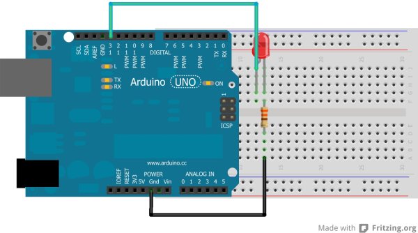 We don’t really need schematics for our early projects as they’re fairly easy to build, but I’d like to use these to start introducing you to them, as they’re going to become very useful later in the book. So without further ado, let me introduce you to the schematic for the Blink project:It’s pretty straight-forward, don’t you think? On the left are the Arduino’s pins – can you spot the 6 Analog pins (A0 – A5) at the top, the 14 Digital pins (0 – 13), and finally the power – GND, 3.3V and 5V connections? As this is not a physical design, you’ll notice that the Arduino pins aren’t set out in the same way that they are physically arranged on the Arduino itself. Let’s get straight into understanding what the schematic is telling us. Start by finding pin 13.
The current flows from pin 13 (which in this project is being used as an OUTPUT pin) to LED1. The straight line represents a connection between the pin and LED1: this could be a wire, a track on a breadboard, or a printed track on a circuit board. Look at the parts list at the beginning of the chapter, and you’ll see that LED1 is the label for an LED (pretty obvious in this case, but not always!) If you don’t already, you’ll start recognising the symbols for these components as we work through our projects – the symbols are also in the component reference at the end of the book.
From LED1, the current flows to R1. This label is a little more cryptic, so refer to the parts list, and you’ll see it’s a Resistor, with a resistance of 330 Ohm. It’s a good idea to show the value of resistors, capacitors, etc. on schematics, as it helps others to build the circuit correctly.From the resistor, the current flows to the GND pin on the Arduino – GND being the same as the negative terminal on a battery – and completes the circuit.
 Breadboard Diagram
Now that you understand how the parts connect together, let’s look at one way to lay them out physically on a breadboard.
The above is the first look that you’ve had at how the “theoretical” flow relates to the physical world. I find it much easier to understand things when I see them physically – often schematics can be a little too vague and hypothetical to me. I want to see what the circuit looks like and how I’m going to physically build it.
For more detail: Arduino Tutorial – Chapter 2.3: Schematic and Breadboard Diagrams
- What is the purpose of a schematic diagram?
It serves as an architect's plan that allows anyone to look at the drawing and build the circuit using specific component symbols. - How does current flow in the Blink project schematic?
The current flows from pin 13 to LED1, then to R1, and finally to the GND pin on the Arduino. - Why are resistor values shown on schematics?
Showing values helps others build the circuit correctly. - Does the schematic layout match the physical arrangement of Arduino pins?
No, the Arduino pins in the schematic are not set out in the same way they are physically arranged on the board. - What label is used for the LED in this project?
The label used for the LED is LED1. - What does the straight line represent in the schematic?
A straight line represents a connection between the pin and a component, which could be a wire, a track on a breadboard, or a printed track on a circuit board. - Why might someone prefer a breadboard diagram over a schematic?
Schematics can be vague and hypothetical, while breadboard diagrams show what the circuit looks like and how to physically build it.