Summary of Arduino Timer and Interrupt Tutorial
This tutorial explains Arduino timers and interrupts: their types (Timer0/1/2 and Timer3/4/5 on Mega), registers (TCCRx, TCNTx, OCRx, ICRx, TIMSKx, TIFRx), clock/prescaler calculations, timer modes (PWM, CTC), interrupt types (overflow, compare match, input capture), PWM-pin mappings, useful libraries, and examples (Timer1 compare match and overflow LED blink, Timer2-based quadrature encoder). It shows code and configuration details for using timer interrupts and cautions about altering Timer0 which affects Arduino timing functions.
Parts used in theArduino Timer and Interrupt Tutorial:
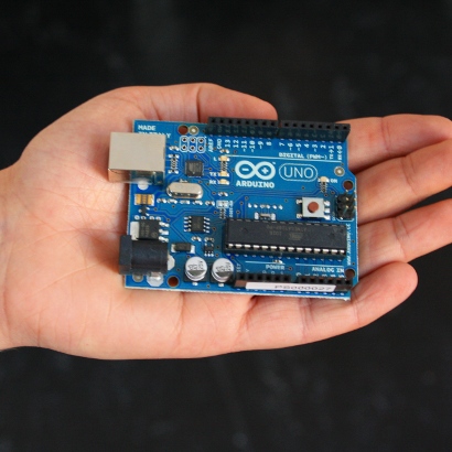
- Arduino board (ATmega168/328 based Uno or compatible)
- Arduino Mega board (ATmega1280/2560) (for timers 3,4,5)
- LED (example uses pin 13)
- Quadrature encoders (Pololu wheel encoders in example)
- Wires and basic prototyping connections
- Computer with Arduino IDE (for uploading code)
Arduino Timer and Interrupt Tutorial
This tutorial shows the use of timers and interrupts for Arduino boards. As Arduino programmer you have probably used timers and interrupts without even knowing it’s there, because all the low level hardware stuff is hidden by the Arduino API. Many Arduino functions uses timers, for example the time functions: delay(), millis() and micros(), the PWM functions analogWrite(), the tone() and the noTone() function, even the Servo library uses timers and interrupts.
What is a timer?
A timer, A.K.A. counter is a piece of hardware built in the Arduino controller. It is like a clock, and can be used to measure time events.
The timer can be programmed by some special registers. You can configure the pre-scaler for the timer, or the mode of operation and many other things.
The Arduino board is based on the Atmel AVR ATmega168 or the ATmega328 microchip. These chips are pin compatible and only differ in the size of internal memory. Both have 3 timers, called Timer0, Timer1 and Timer2. Timer0 and Timer2 are 8bit timer, where Timer1 is a 16bit timer.
The most important difference between 8bit and 16bit timer is the timer resolution. 8bits means 256 values (two to the power of 8) where 16bit means 65536 values (two to the power of 16) which is much higher resolution.
The Arduino Mega series is based on the Atmel AVR ATmega1280 or the ATmega2560. They are almost identical to previous chips but only differs in memory size. These chips have 6 timers. First 3 timers (Timer 0, Timer1 and Timer2) are identical to the ATmega168/328. Timer3, Timer4 and Timer5 are all 16bit timers, similar to Timer1.
All timers depends on the system clock of your Arduino system. Normally the system clock is 16MHz, but the Arduino Pro 3/3V is 8Mhz, so be careful when writing your own timer functions.
The timer hardware can be configured with some special timer registers. In the Arduino firmware, all timers were configured to a 1kHz frequency and interrupts are generally enabled.
To summarize:
Timer0:
 Timer0 is a 8bit timer.
 In the Arduino world Timer0 is been used for the timer functions, like delay(), millis() and micros(). If you change Timer0 registers, this may influence the Arduino timer function. So you should know what you are doing.
Timer1:
 Timer1 is a 16bit timer.
 In the Arduino world the Servo library uses Timer1 on Arduino Uno (Timer5 on Arduino Mega).
Timer2:
 Timer2 is a 8bit timer like Timer0.
 In the Arduino work the tone() function uses Timer2.
Timer3, Timer4, Timer5: Timer 3,4,5 are only available on Arduino Mega boards. These timers are all 16bit timers.
Timer Register
You can change the Timer behaviour through the timer register. The most important timer registers are:
-
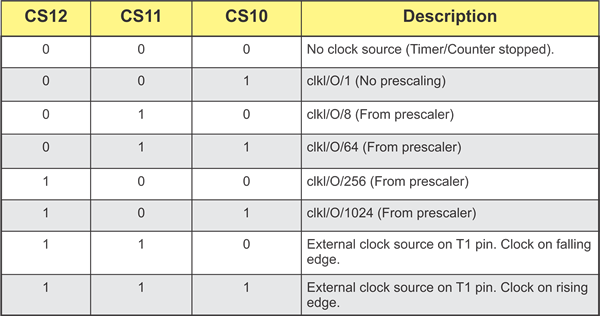
TCCRx - Timer/Counter Control Register. The pre-scaler can be configured here.
-
TCNTx - Timer/Counter Register. The actual timer value is stored here.
-
OCRx - Output Compare Register
-
ICRx - Input Capture Register (only for 16bit timer)
-
TIMSKx - Timer/Counter Interrupt Mask Register. To enable/disable timer interrupts.
-
TIFRx - Timer/Counter Interrupt Flag Register. Indicates a pending timer interrupt.
Clock select and timer frequency
Different clock sources can be selected for each timer independently. To calculate the timer frequency (for example 2Hz using Timer1) you will need:
1. CPU frequency 16Mhz for Arduino
2. maximum timer counter value (256 for 8bit, 65536 for 16bit timer)
3. Divide CPU frequency through the chosen pre-scaler (16000000 / 256 = 62500)
4. Divide result through the desired frequency (62500 / 2Hz = 31250)
5. Verify the result against the maximum timer counter value (31250 < 65536 success) if fail, choose bigger pre-scaler.
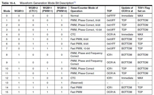
Timer modes
Timers can be configured in different modes.
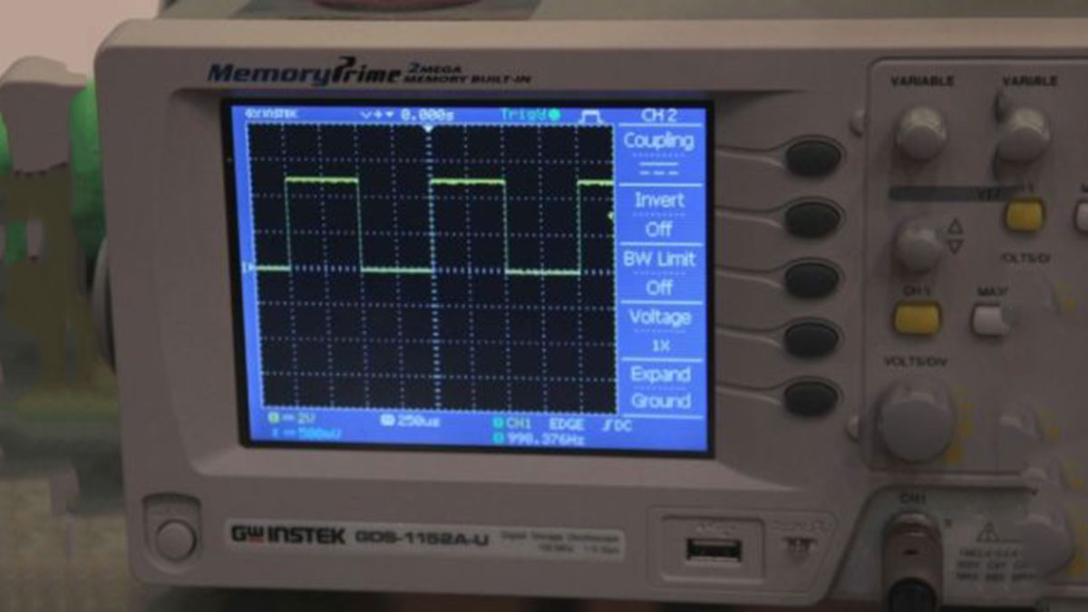
PWM (Pulse width modulation) mode – the OCxy outputs are used to generate PWM signals
CTC (Clear timer on compare match) mode – When the timer counter reaches the compare match register, the timer will be cleared.
What is an interrupt?
The program running on a controller is normally running sequentially instruction by instruction. An interrupt is an external event that interrupts the running program and runs a special interrupt service routine (ISR). After the ISR has been finished, the running program is continued with the next instruction. Instruction means a single machine instruction, not a line of C or C++ code.
Before an pending interrupt will be able to call a ISR the following conditions must be true:
- Interrupts must be generally enabled
- the according Interrupt mask must be enabled
Interrupts can generally enabled or disabled with the function interrupts() or noInterrupts(). By default in the Arduino firmware interrupts are enabled. Interrupt masks are enabled / disabled by setting or clearing bits in the Interrupt mask register (TIMSKx).
When an interrupt occurs, a flag in the interrupt flag register (TIFRx) is been set. This interrupt will be automatically cleared when entering the ISR or by manually clearing the bit in the interrupt flag register.
The Arduino functions attachInterrupt() and detachInterrupt() can only be used for external interrupt pins. These are different interrupt sources, not discussed here.
Timer interrupts
A timer can generate different types of interrupts. The register and bit definitions can be found in the processor data sheet (Atmega328 or Atmega2560) and in the I/O definition header file (iomx8.h for Arduino, iomxx0_1.h for Arduino Mega in the hardware/tools/avr/include/avr folder). The suffix x stands for the timer number (0..5), the suffix y stands for the output number (A,B,C), for example TIMSK1 (Timer1 interrupt mask register) or OCR2A (Timer2 output compare register A).
Timer Overflow:
Timer overflow means the timer has reached is limit value. When a timer overflow interrupt occurs, the timer overflow bit TOVx will be set in the interrupt flag register TIFRx. When the timer overflow interrupt enable bit TOIEx in the interrupt mask register TIMSKx is set, the timer overflow interrupt service routine ISR(TIMERx_OVF_vect) will be called.
Output Compare Match:
When a output compare match interrupt occurs, the OCFxy flag will be set in the interrupt flag register TIFRx . When the output compare interrupt enable bit OCIExy in the interrupt mask register TIMSKx is set, the output compare match interrupt service ISR(TIMERx_COMPy_vect) routine will be called.
Timer Input Capture:
When a timer input capture interrupt occurs, the input capture flag bit ICFx will be set in the interrupt flag register TIFRx. When the input capture interrupt enable bit ICIEx in the interrupt mask register TIMSKx is set, the timer input capture interrupt service routine ISR(TIMERx_CAPT_vect) will be called.
PWM and timer
There is fixed relation between the timers and the PWM capable outputs. When you look in the data sheet or the pinout of the processor these PWM capable pins have names like OCRxA, OCRxB or OCRxC (where x means the timer number 0..5). The PWM functionality is often shared with other pin functionality.
The Arduino has 3 timers and 6 PWM output pins. The relation between timers and PWM outputs is:
- Pins 5 and 6: controlled by Timer0
- Pins 9 and 10: controlled by Timer1
- Pins 11 and 3: controlled by Timer2
On the Arduino Mega we have 6 timers and 15 PWM outputs:
- Pins 4 and 13: controlled by Timer0
- Pins 11 and 12: controlled by Timer1
- Pins 9 and10: controlled by Timer2
- Pin 2, 3 and 5: controlled by timer 3
- Pin 6, 7 and 8: controlled by timer 4
- Pin 46, 45 and 44:: controlled by timer 5
Usefull 3rd party libraries
Some 3rd party libraries exists, that uses timers:
- Ken Shirrifs IR library using Timer2 – Send and receive any kind of IR remote signals
- Timer1 and Timer3 library using Timer1 or tiner3 – easy way to write your own timer interrupt service routines.
Examples
Blinking LED with compare match interrupt
The first example uses the Timer1 in CTC mode and the compare match interrupt to toggle a LED. The timer is configured for a frequency of 2Hz. The LED is toggled in the interrupt service routine.

/*
* timer and interrupts
* Timer1 compare match interrupt example
* more infos: https://oscarliang.com
*/
#define ledPin 13
void setup()
{
pinMode(ledPin, OUTPUT);
// initialize Timer1
noInterrupts(); // disable all interrupts
TCCR1A = 0;
TCCR1B = 0;
TCNT1 = 0;
OCR1A = 31250; // compare match register 16MHz/256/2Hz
TCCR1B |= (1 << WGM12); // CTC mode
TCCR1B |= (1 << CS12); // 256 prescaler
TIMSK1 |= (1 << OCIE1A); // enable timer compare interrupt
interrupts(); // enable all interrupts
}
ISR(Timer1_COMPA_vect) // timer compare interrupt service routine
{
digitalWrite(ledPin, digitalRead(ledPin) ^ 1); // toggle LED pin
}
void loop()
{
// your program here…
}
Blinking LED with timer overflow interrupt
same example like before but now we use the timer overflow interrupt. In this case Timer1 is running in normal mode.
The timer must be pre loaded every time in the interrupt service routine.
[sourcecode language=”cpp”] /** timer and interrupts
* Timer1 overflow interrupt example
* more infos: https://oscarliang.com
*/
#define ledPin 13
void setup()
{
pinMode(ledPin, OUTPUT);
// initialize Timer1
noInterrupts(); // disable all interrupts
TCCR1A = 0;
TCCR1B = 0;
TCNT1 = 34286; // preload timer 65536-16MHz/256/2Hz
TCCR1B |= (1 << CS12); // 256 prescaler
TIMSK1 |= (1 << TOIE1); // enable timer overflow interrupt
interrupts(); // enable all interrupts
}
ISR(Timer1_OVF_vect) // interrupt service routine that wraps a user defined function supplied by attachInterrupt
{
TCNT1 = 34286; // preload timer
digitalWrite(ledPin, digitalRead(ledPin) ^ 1);
}
void loop()
{
// your program here…
}
Reading quadrature encoders with a timer
The next example uses Timer2 and the compare match interrupt to read the encoder inputs.
Timer2 is initialized by default to a frequency of 1kHz (1ms period). In the interrupt service routine the state of all encoder pins is read and a state machine is used to eliminate false readings. Using the timer interrupt is much easier to handle than using 4 input change interrupts.
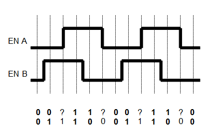
The signals of a quadrature encoder is a 2bit Gray code. Only 1 bit is changing from state to state. A state machine is perfect to check the signal and count the encoder ticks. The timer must be fast enough, to recognize each state change. For the Pololu wheel encoders used here, the 1ms timer is fast enough.
The following example has been modified to work with Arduino V1.x
/*
* timer and interrupts
* Timer2 compare interrupt example. Quadrature Encoder
* more infos: https://oscarliang.com
*
* Credits:
* based on code from Peter Dannegger
* http://www.mikrocontroller.net/articles/Drehgeber
*/
#if ARDUINO >= 100
#include “Arduino.h”
#else
#include “WConstants.h”
#endif
// Encoder Pins
#define encLtA 2
#define encLtB 3
#define encRtA 11
#define encRtB 12
#define ledPin 13
#define LT_PHASE_A digitalRead(encLtA)
#define LT_PHASE_B digitalRead(encLtB)
#define RT_PHASE_A digitalRead(encRtA)
#define RT_PHASE_B digitalRead(encRtB)
static volatile int8_t encDeltaLt, encDeltaRt;
static int8_t lastLt, lastRt;
int encLt, encRt;
ISR( Timer2_COMPA_vect )
{
int8_t val, diff;
digitalWrite(ledPin, HIGH); // toggle LED pin
val = 0;
if( LT_PHASE_A )
val = 3;
if( LT_PHASE_B )
val ^= 1; // convert gray to binary
diff = lastLt – val; // difference last – new
if( diff & 1 ){ // bit 0 = value (1)
lastLt = val; // store new as next last
encDeltaLt += (diff & 2) – 1; // bit 1 = direction (+/-)
}
val = 0;
if( RT_PHASE_A )
val = 3;
if( RT_PHASE_B )
val ^= 1; // convert gray to binary
diff = lastRt – val; // difference last – new
if( diff & 1 ){ // bit 0 = value (1)
lastRt = val; // store new as next last
encDeltaRt += (diff & 2) – 1; // bit 1 = direction (+/-)
}
digitalWrite(ledPin, LOW); // toggle LED pin
}
void QuadratureEncoderInit(void)
{
int8_t val;
cli();
TIMSK2 |= (1<<OCIE2A);
sei();
pinMode(encLtA, INPUT);
pinMode(encRtA, INPUT);
pinMode(encLtB, INPUT);
pinMode(encRtB, INPUT);
val=0;
if (LT_PHASE_A)
val = 3;
if (LT_PHASE_B)
val ^= 1;
lastLt = val;
encDeltaLt = 0;
val=0;
if (RT_PHASE_A)
val = 3;
if (RT_PHASE_B)
val ^= 1;
lastRt = val;
encDeltaRt = 0;
encLt = 0;
encRt = 0;
}
int8_t QuadratureEncoderReadLt( void ) // read single step encoders
{
int8_t val;
cli();
val = encDeltaLt;
encDeltaLt = 0;
sei();
return val; // counts since last call
}
int8_t QuadratureEncoderReadRt( void ) // read single step encoders
{
int8_t val;
cli();
val = encDeltaRt;
encDeltaRt = 0;
sei();
return val; // counts since last call
}
void setup()
{
Serial.begin(38400);
pinMode(ledPin, OUTPUT);
QuadratureEncoderInit();
}
void loop()
{
encLt += QuadratureEncoderReadLt();
encRt += QuadratureEncoderReadRt();
Serial.print(“Lt: “);
Serial.print(encLt, DEC);
Serial.print(” Rt: “);
Serial.println(encRt, DEC);
delay(1000);
}
Source : Arduino Timer and Interrupt Tutorial
- What timers are available on Arduino Uno?
Timer0 and Timer2 are 8bit timers and Timer1 is a 16bit timer on ATmega168/328 based boards. - Can I change Timer0 behavior without consequences?
Changing Timer0 registers may influence Arduino timing functions like delay(), millis() and micros(). - How do I calculate timer settings for a desired frequency?
Use CPU frequency, maximum counter value, divide by chosen prescaler, divide by desired frequency and verify result against max counter value. - What timer modes are commonly used?
PWM mode for PWM outputs and CTC (clear timer on compare match) mode are commonly used. - How do timer interrupts get enabled?
Enable global interrupts and set the appropriate interrupt mask bit in TIMSKx for the desired timer interrupt. - Which Arduino pins are controlled by Timer1 PWM outputs?
On Arduino Uno pins 9 and 10 are controlled by Timer1; on Arduino Mega pins 11 and 12 are controlled by Timer1. - Does the tutorial include example code for blinking an LED using timers?
Yes, it includes Timer1 compare match and Timer1 overflow examples that toggle an LED on pin 13. - What is recommended for reading quadrature encoders?
Use a timer interrupt (example uses Timer2 at 1kHz) and a state machine to read encoder pins and avoid false readings. - Are there third party libraries that use timers?
Yes, examples given are Ken Shirriffs IR library using Timer2 and Timer1/Timer3 libraries for easy timer interrupts.