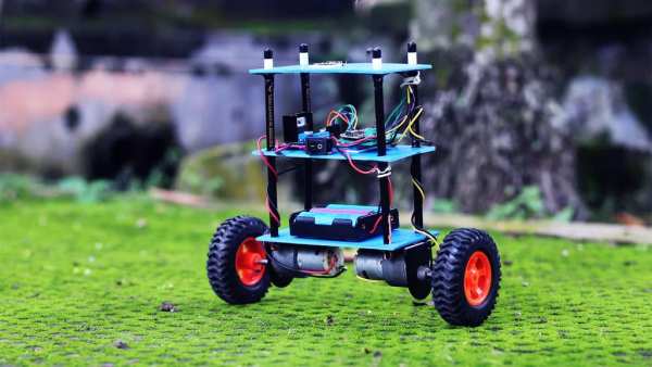
Today in this tutorial, I have made a SELF-BALANCING robot with ARDUINO. I hope this article will help the beginners to make it properly
Supplies
For the mechanical Part, we will need
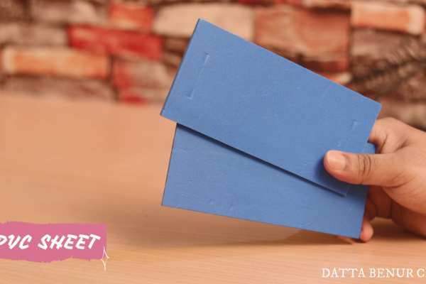
- PVC SHEET
- GRAPHITE PENCILS
- GEAR MOTOR
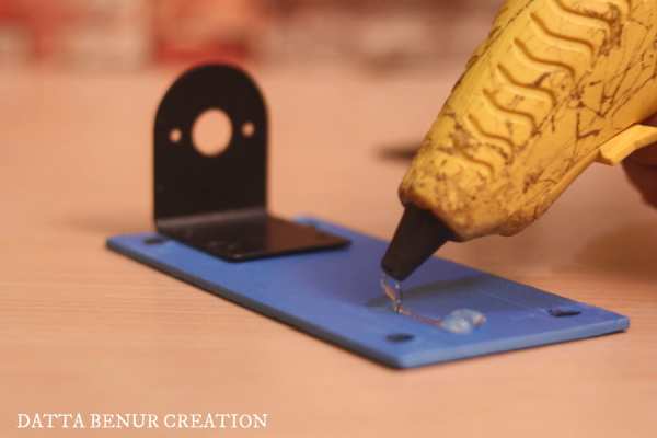
- MOTOR BRACKET
- WHEELS
For The Electronics Part, we will need
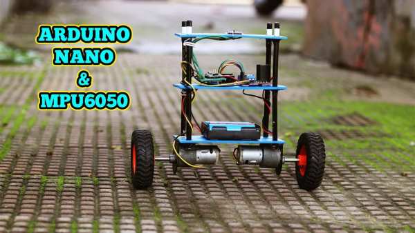
- Arduino Nano
- L298n motor driver
- MPU6050 module
- 18650 Li-ion Battery
- 18650 Li-ion battery Holder
- Rocker Switch
Step 1: WHAT IS a SELF-BALANCING ROBOT?
A self-balancing robot is a two-wheeled robot that balances itself so that it prevents itself from falling.
Step 2: HOW DOES a SELF-BALANCING ROBOT WORKS?
Self-balancing robots use a “closed-loop feedback control” system; this means that real-time data from motion sensors are used to control the motors and quickly compensate for any tilting motion in order to keep the robot upright. Similar self-balancing feedback control systems can be seen in many other applications.
Step 3: WHERE ARE SELF-BALANCING ROBOTS USED?
Among wheeled robots, two self-balancing robots, the Segway and Ninebot, have become popular and are used for commuting or as patrol transporters. In addition, self-balancing wheeled robots such as Anybots QB are currently used as a service robot platform.
Step 4: WHICH COMPONENTS WILL BE NEEDED AND WHY?
Here in this part, we will discuss the components, why we did choose them, and side by side we will make the robot too.
for a better explanation, I have divided this into three different parts-
- Mechanical Part:- here we will learn to make the robot body in a very simple and easy way.
- Electronics Part:- here we will learn about the electronics components, circuit designing, and assembling all the components. end of this part, our robot will be ready to go for the next and last level which is Arduino coding and calibration.
- Arduino Coding & Calibration:- Here in this last part, we will discuss the Arduino code and how to calibrate the robot for self-balancing.
After completing these three steps, Our robot will be ready to show.
Step 5: MECHANICAL PART
We will start making our mechanical part first. For this, l have used some PVC sheets and 4 no of Graphite Pencil to make the robot Body. Please make the robot multi-storied because we are going to use mpu6050 which works best if it is placed at some height upper than the base. We will discuss more on mpu6050 in the later part of the electronics part of this article. For now, we will go for the mechanical part only. After that, we will need two no of gear motors, two motor brackets, and two wheels.
I have used hot glue to attach all the parts together. It will take not more than 20-25min to give it a perfect look like this. Our mechanical part is ready and now we will go for the electronics part.
Step 6: ELECTRONICS PART
In this part, we will discuss the electronic components that we have used to make this robot. We will also learn why have we chosen all these components. Here we will also connect all the components together according to the circuit diagram that l have already attached with this article. Please download it before you are going to connect all the components together.
ARDUINO NANO
Arduino NANO is the brain of the robot. Here l choose it because It’s a perfect micro controller to learn hobby electronics and programming on, and its size makes it excellent for building into projects which require a small form factor.
L298n Motor Driver
The L298N Motor Driver is a controller that uses an H-Bridge to easily control the direction and speed of up to 2 DC motors. The L298N is a dual H-Bridge motor driver which allows speed and direction control of two DC motors at the same time. The module can drive DC motors that have voltages between 5 and 35V, with a peak current up to 2A.
MPU6050
MPU6050 is a Micro Electro-mechanical system (MEMS), it consists of a three-axis accelerometer and a three-axis gyroscope. which means that it gives six values as output:
- three values from the accelerometer
- three from the gyroscope
It helps us to measure velocity, orientation, acceleration, displacement, and other motion-like features. It is very accurate, as it contains a 16-bits analog to digital conversion hardware for each channel. Therefore it captures the x, y, and z channels at the same time. The sensor uses the I2C-bus to interface with the Arduino. The MPU6050 can measure angular rotation using its on-chip gyroscope with four programmable full-scale ranges of ±250°/s, ±500°/s, ±1000°/s, and ±2000°/s.
These were the basic details of the components that I have used in this robot. There have many more components like Rocker switches, Jumper Wires, etc many more things which have no need for explanation l belief. Now l am going for the next step
Step 7: ASSEMBLE COMPONENTS TOGETHER
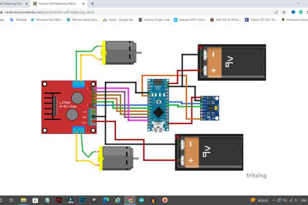
As I have already mentioned before I have already attached a circuit diagram with this article so please download that before you are going to connect all of them together. In my case, I have made a customized PCB board from JLCPCB to skip a few steps of wiring and make an easy connection between all the components.$2 for 5pcs PCBs, PCBA from $0, Register to Get Free Coupons here: https://jlcpcb.com/IYB. I really liked the PCB Boards as they are very high in quality.
I have placed Arduino nano and MPU6050 on the same circuit board and also I have made a separate point for HC-05 Bluetooth Module so that I could easily upgrade my Self-Balancing Robot into a Bluetooth Controlled Self-Balanced Robot in my next project with the same PCB Board. I have just excluded the l298n motor driver module from my Customized PCB board. That portion will need to be wiring only.
here you can see that I have already done wiring the components together. The next step is very simple which is to collage the mechanical part and electronic part together and also have to connect a battery holder switch and 18650 li-ion battery with the robot body and the circuit. let’s do that…
by installing all the components perfectly in the robot body, we have done making our robot. now only the last and final step has left to do which is Uploading Arduino code to the Arduino Nano.
Step 8: ARDUINO CODING AND CALIBRATION
There have to follow a few steps to calibrate & uploading the code…
for better understanding, l have divided this Arduino coding and calibration part into some different parts.
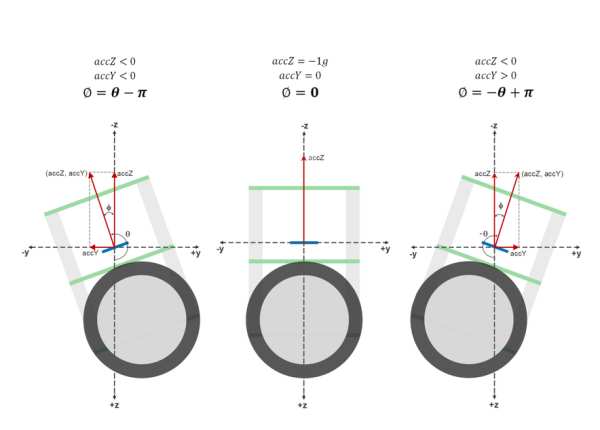
- Measuring Angle of Inclination Using Accelerometer
The MPU6050 has a 3-axis accelerometer and a 3-axis gyroscope. The accelerometer measures acceleration along the three axes and the gyroscope measures angular rate about the three axes. To measure the angle of inclination of the robot we need acceleration values along the y and z-axes. The atan2(y,z) function gives the angle in radians between the positive z-axis of a plane and the point given by the coordinates (z,y) on that plane, with the positive sign for counter-clockwise angles (right half-plane, y > 0), and negative sign for clockwise angles (left half-plane, y < 0). We use this library written by Jeff Rowberg to read the data from MPU6050. Upload the code given below and see how the angle of inclination varies.
#include "Wire.h"
#include "I2Cdev.h"
#include "MPU6050.h"
#include "math.h"
MPU6050 mpu;
int16_t accY, accZ;
float accAngle;
void setup() {
  mpu.initialize();
  Serial.begin(9600);
}
void loop() {
  accZ = mpu.getAccelerationZ();
  accY = mpu.getAccelerationY();

  accAngle = atan2(accY, accZ)*RAD_TO_DEG;

  if(isnan(accAngle));
  else
    Serial.println(accAngle);
}
Try moving the robot forward and backward while keeping it tilted at some fixed angle. You will observe that the angle is shown in your serial monitor suddenly changes. This is due to the horizontal component of acceleration interfering with the acceleration values of y and z-axes.
- Measuring Angle of Inclination Using Gyroscope
The 3-axis gyroscope of MPU6050 measures angular rate (rotational velocity) along the three axes. For our self-balancing robot, the angular velocity along the x-axis alone is sufficient to measure the rate of fall of the robot.
In the code given below, we read the gyro value about the x-axis, convert it to degrees per second and then multiply it with the loop time to obtain the change in angle. We add this to the previous angle to obtain the current angle.
#include "Wire.h"
#include "I2Cdev.h"
#include "MPU6050.h"
MPU6050 mpu;
int16_t gyroX, gyroRate;
float gyroAngle=0;
unsigned long currTime, prevTime=0, loopTime;
void setup() {
  mpu.initialize();
  Serial.begin(9600);
}
void loop() {
  currTime = millis();
  loopTime = currTime - prevTime;
  prevTime = currTime;

  gyroX = mpu.getRotationX();
  gyroRate = map(gyroX, -32768, 32767, -250, 250);
  gyroAngle = gyroAngle + (float)gyroRate*loopTime/1000;

  Serial.println(gyroAngle);
}
The position of the MPU6050 when the program starts running is the zero inclination point. The angle of inclination will be measured with respect to this point.
Keep the robot steady at a fixed angle and you will observe that the angle will gradually increase or decrease. It won’t stay steady. This is due to the drift which is inherent to the gyroscope.
In the code given above, loop time is calculated using the millis() function which is built into the Arduino IDE. In later steps, we will be using timer interrupts to create precise sampling intervals. This sampling period will also be used in generating the output using a PID controller.
- Combining the Results With a Complementary Filter
Google defines complementary as “combining in such a way as to enhance or emphasize the qualities of each other or another”.
We have two measurements of the angle from two different sources. The measurement from the accelerometer gets affected by sudden horizontal movements and the measurement from the gyroscope gradually drifts away from the actual value. In other words, the accelerometer reading gets affected by short-duration signals and the gyroscope reading by long-duration signals. These readings are, in a way, complementary to each other. Combine them both using a Complementary Filter and we get a stable, accurate measurement of the angle. The complementary filter is essentially a high pass filter acting on the gyroscope and a low pass filter acting on the accelerometer to filter out the drift and noise from the measurement.
currentAngle = 0.9934 * (previousAngle + gyroAngle) + 0.0066 * (accAngle)
0.9934 and 0.0066 are filter coefficients for a filter time constant of 0.75s. The low pass filter allows any signal longer than this duration to pass through it and the high pass filter allows any signal shorter than this duration to pass through. The response of the filter can be tweaked by picking the correct time constant. Lowering the time constant will allow more horizontal acceleration to pass through.
Eliminating accelerometer and gyroscope offset errors
Download and run the code given on this page to calibrate the MPU6050’s offsets. Any error due to offset can be eliminated by defining the offset values in the setup() routine as shown below.
mpu.setYAccelOffset(1593);
mpu.setZAccelOffset(963);
mpu.setXGyroOffset(40);
- PID Control for Generating Output
PID stands for Proportional, Integral, and Derivative. Each of these terms provides a unique response to our self-balancing robot.
The proportional term, as its name suggests, generates a response that is proportional to the error. For our system, the error is the angle of inclination of the robot.
The integral term generates a response based on the accumulated error. This is essentially the sum of all the errors multiplied by the sampling period. This is a response based on the behavior of the system in past.
The derivative term is proportional to the derivative of the error. This is the difference between the current error and the previous error divided by the sampling period. This acts as a predictive term that responds to how the robot might behave in the next sampling loop.
Multiplying each of these terms by their corresponding constants (i.e, Kp, Ki, and Kd) and summing the result, we generate the output which is then sent as a command to drive the motor.
- Tuning the PID Constants
1. Set Ki and Kd to zero and gradually increase Kp so that the robot starts to oscillate about the zero position.
2. Increase Ki so that the response of the robot is faster when it is out of balance. Ki should be large enough so that the angle of inclination does not increase. The robot should come back to zero position if it is inclined.
3. Increase Kd so as to reduce the oscillations. The overshoots should also be reduced by now.
4. Repeat the above steps by fine-tuning each parameter to achieve the best result.
- The Complete Code
//Self Balancing Robot
#include<Arduino.h>
#include <PID_v1.h>
#include <LMotorController.h>
#include "I2Cdev.h"
#include "MPU6050_6Axis_MotionApps20.h"

#if I2CDEV_IMPLEMENTATION == I2CDEV_ARDUINO_WIRE
#include "Wire.h"
#endif

#define MIN_ABS_SPEED 30

MPU6050 mpu;

// MPU control/status vars
bool dmpReady = false; // set true if DMP init was successful
uint8_t mpuIntStatus; // holds actual interrupt status byte from MPU
uint8_t devStatus; // return status after each device operation (0 = success, !0 = error)
uint16_t packetSize; // expected DMP packet size (default is 42 bytes)
uint16_t fifoCount; // count of all bytes currently in FIFO
uint8_t fifoBuffer[64]; // FIFO storage buffer

// orientation/motion vars
Quaternion q; // [w, x, y, z] quaternion container
VectorFloat gravity; // [x, y, z] gravity vector
float ypr[3]; // [yaw, pitch, roll] yaw/pitch/roll container and gravity vector

//PID
double originalSetpoint = 172.50;
double setpoint = originalSetpoint;
double movingAngleOffset = 0.1;
double input, output;

//adjust these values to fit your own design
double Kp = 60;
double Kd = 2.2;
double Ki = 270;
PID pid(&input, &output, &setpoint, Kp, Ki, Kd, DIRECT);

double motorSpeedFactorLeft = 0.6;
double motorSpeedFactorRight = 0.5;

//MOTOR CONTROLLER
int ENA = 5;
int IN1 = 6;
int IN2 = 7;
int IN3 = 9;
int IN4 = 8;
int ENB = 10;
LMotorController motorController(ENA, IN1, IN2, ENB, IN3, IN4, motorSpeedFactorLeft, motorSpeedFactorRight);

volatile bool mpuInterrupt = false; // indicates whether MPU interrupt pin has gone high
void dmpDataReady()
{
  mpuInterrupt = true;
}


void setup()
{
  // join I2C bus (I2Cdev library doesn't do this automatically)
#if I2CDEV_IMPLEMENTATION == I2CDEV_ARDUINO_WIRE
  Wire.begin();
  TWBR = 24; // 400kHz I2C clock (200kHz if CPU is 8MHz)
#elif I2CDEV_IMPLEMENTATION == I2CDEV_BUILTIN_FASTWIRE
  Fastwire::setup(400, true);
#endif

  mpu.initialize();

  devStatus = mpu.dmpInitialize();

  // supply your own gyro offsets here, scaled for min sensitivity
  mpu.setXGyroOffset(220);
  mpu.setYGyroOffset(76);
  mpu.setZGyroOffset(-85);
  mpu.setZAccelOffset(1788); // 1688 factory default for my test chip

  // make sure it worked (returns 0 if so)
  if (devStatus == 0)
  {
    // turn on the DMP, now that it's ready
    mpu.setDMPEnabled(true);

    // enable Arduino interrupt detection
    attachInterrupt(0, dmpDataReady, RISING);
    mpuIntStatus = mpu.getIntStatus();

    // set our DMP Ready flag so the main loop() function knows it's okay to use it
    dmpReady = true;

    // get expected DMP packet size for later comparison
    packetSize = mpu.dmpGetFIFOPacketSize();

    //setup PID
    pid.SetMode(AUTOMATIC);
    pid.SetSampleTime(10);
    pid.SetOutputLimits(-255, 255);
  }
  else
  {
    // ERROR!
    // 1 = initial memory load failed
    // 2 = DMP configuration updates failed
    // (if it's going to break, usually the code will be 1)
    Serial.print(F("DMP Initialization failed (code "));
    Serial.print(devStatus);
    Serial.println(F(")"));
  }
}


void loop()
{
  // if programming failed, don't try to do anything
  if (!dmpReady) return;

  // wait for MPU interrupt or extra packet(s) available
  while (!mpuInterrupt && fifoCount < packetSize)
  {
    //no mpu data - performing PID calculations and output to motors
    pid.Compute();
    motorController.move(output, MIN_ABS_SPEED);

  }

  // reset interrupt flag and get INT_STATUS byte
  mpuInterrupt = false;
  mpuIntStatus = mpu.getIntStatus();

  // get current FIFO count
  fifoCount = mpu.getFIFOCount();

  // check for overflow (this should never happen unless our code is too inefficient)
  if ((mpuIntStatus & 0x10) || fifoCount == 1024)
  {
    // reset so we can continue cleanly
    mpu.resetFIFO();
    Serial.println(F("FIFO overflow!"));

    // otherwise, check for DMP data ready interrupt (this should happen frequently)
  }
  else if (mpuIntStatus & 0x02)
  {
    // wait for correct available data length, should be a VERY short wait
    while (fifoCount < packetSize) fifoCount = mpu.getFIFOCount();

    // read a packet from FIFO
    mpu.getFIFOBytes(fifoBuffer, packetSize);

    // track FIFO count here in case there is > 1 packet available
    // (this lets us immediately read more without waiting for an interrupt)
    fifoCount -= packetSize;

    mpu.dmpGetQuaternion(&q, fifoBuffer);
    mpu.dmpGetGravity(&gravity, &q);
    mpu.dmpGetYawPitchRoll(ypr, &q, &gravity);
    input = ypr[1] * 180 / M_PI + 180;
  }
}
Step 9: DIY VIDEO
here we have done making the project of Arduino Self-Balancing Robot successfully… Now it’s show time. Please Click Below To watch the full procedure and the outcome…
https://www.youtube.com/watch?v=tsQludfCmfA
Source: Arduino SELF-BALANCING Robot