Summary of Arduino Password Unlock Door Security System
This guide details building an Arduino Uno-based password-protected door unlock system. The device allows users to enter a code via a 4x4 keypad to open an electric lock for five seconds, with features to change passwords or cancel operations using specific buttons. A buzzer provides audio feedback, and the circuit can be built on a breadboard or as a custom ATmega328 board.
Parts used in the Arduino Password Unlock Door System:
- Arduino uno board
- High contrast LCD display 16x2
- Keypad 4x4
- 10~20k potentiometer
- NPN transistor NP2222A
- 2 pins screw driver circuit
- Electric door opener (12V)
- Power source 9 to 12V
- DIP socket for atmega328
- LM7805 Voltage regulator (5V output)
- 16Mhz crystal osc
- 2x 22pF ceramic capacitors
- 2x 0.22uF electrolytic capacitors
- 1x 10K resistor
- DC power jack
- pcb prototyping board
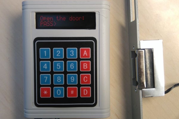
Hello! In this Instructables guide I will show you how to make your own password unlock door system by using the Arduino uno board. I made my own circuit by using the ATmega328 micro controller but this is an optional step. In this guide I will help you to make it easily on breadboard by using the Arduino uno board, and I will give you some extra tips on how you can make your own Arduino-based custom circuit.
By using this system you will be able to unlock a door for 5 seconds. After 5 seconds the electrical door opener will be automatically be locked. You can unlock it by typing the correct password and pressing the ‘*’ button. If you want to change the current password, you can do it by pressing the ‘A’ button and if you want to skip or abord an operation you can do it by pressing the ‘#’ button. It also has a buzzer for making various tones during operation.
Watch the operation video:
The electrical door opener that I used need 9 to 12V to operate. So for this system I used an 12V power adapter. As current passes through it, the electric lock remains open. Otherwise it remains closed.
This device was made only for educational and presentational purpose reasons, it can’t be used in real life. If you want to use it on your home’s door make sure that it’s enough safe , for example use a metal box and put the power cables “inside the wall”.
Let’s get started!
Step 1: What You Will Need
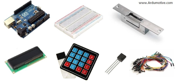
For this project you will need:
- Arduino uno board
- High contrast LCD display 16×2
- Keypad 4×4
- 10~20k potentiometer
- NPN transistor NP2222A
- 2 pins screw driver circuit
- Electric door opener (12V)
- Power source 9 to 12V (max!)
(ONLY) If you want to make your own custom – Arduino based – circuit you willalso need:
- DIP socket for atmega328
- LM7805 Voltage regulator (5V output)
- 16Mhz crystal osc
- 2x 22pF ceramic, 2x 0.22uF electrolytic capacitors
- 1x 10K resistor
- DC power jack
- pcb prototyping board
And one box to fit them all!
Tools:
- Something to cur the plastic box
- Hot glue gun
- Drill for opening holes on the box
Step 2: The Circuit
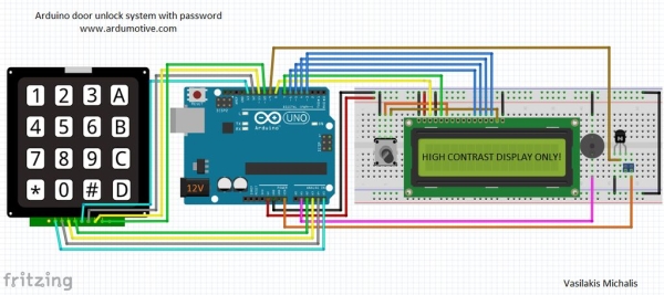
The connections are pretty easy, watch the above image with the breadboard circuit schematic.
Some notes:
High contrast LCD:
- Pin1 – Vdd to GND
- Pin2 – Vss to 5V
- Pin3 – Vo (to middle pin of the potentiometer!)
- Pin4 – RS to Arduino pin 8
- Pin5 – RW to GND
- Pin6 – EN to Arduino pin 7
- Pin11 – D4 to Arduino pin 6
- Pin12 – D5 to Arduino pin 5
- Pin13 – D6 to Arduino pin 4
- Pin14 – D7 to Arduino pin 3
- Pin15 – Vee (to right or left pin of the potentiometer)
Keypad 4×4:
From left to the right pin:
- Pin1 to Arduino pin A5
- Pin2 to Arduino pin A4
- Pin3 to Arduino pin A3
- Pin4 to Arduino pin A2
- Pin5 to Arduino pin 13
- Pin6 to Arduino pin 12
- Pin7 to Arduino pin 11
- Pin8 to Arduino pin 10
NPN Transistor:
- B Base pin to Arduino pin 9
- C Collector pin to 1st pin of the screw driver terminal *
- E Emitter to GND
The 2nd pin of the screw driver terminal will be connected with Arduino “Vin” pin and will give power to our electrical door opener (9V to 12V) .
Read more: Arduino Password Unlock Door Security System
- How long does the electrical door opener stay unlocked?
The system unlocks the door for 5 seconds before automatically locking it again. - What button is used to type the correct password?
You must press the '*' button after typing the correct password to unlock the door. - How can I change the current password?
To change the password, you need to press the 'A' button. - Which button skips or aborts an operation?
Pressing the '#' button will skip or abort an operation. - Does the system include audio feedback?
Yes, the device has a buzzer that makes various tones during operation. - What voltage range is required for the electrical door opener?
The electrical door opener needs 9 to 12V to operate. - Can this system be used for real-life home security?
No, the device was made only for educational and presentational purposes and cannot be used in real life without safety modifications. - What is the purpose of the NPN transistor in the circuit?
The NPN transistor connects the collector to the screw driver terminal which powers the door opener when the base receives a signal from Arduino pin 9.