Introduction
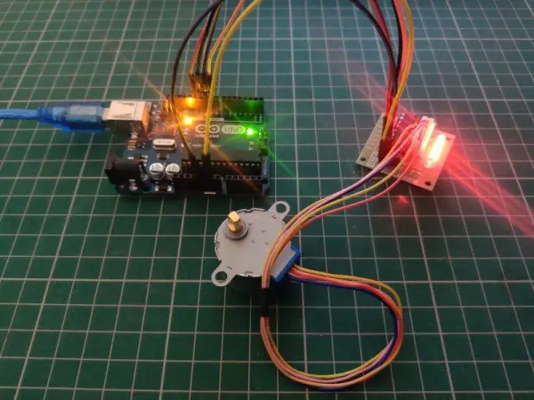
Hello everyone, trust you’re all doing well. This article will guide you through creating a circuit to control a stepper motor using an Arduino UNO and the ULN2003 motor driver. Below, you’ll find three circuit diagrams along with their respective codes. You’re free to choose and create any of these circuits based on your preference. When the stepper motor moves clockwise, it will trigger a message to appear on the LCD screen. Conversely, when it moves counterclockwise, it will display a different status message. Essentially, we’re utilizing Arduino to control the stepper motor. Follow the provided circuit diagrams to establish the connections, and then proceed to upload the code accordingly.
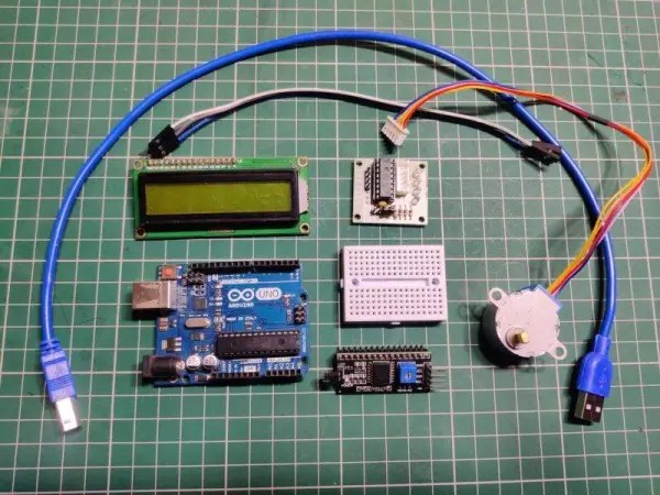
Components Required
Certainly! Here’s a rephrased version of the list:
– Arduino UNO microcontroller board
– ULN2003 driver module for motor control
– Stepper motor for precise motion
– I2C module for communication
– 16×2 LCD display for visual output
– Jumper wires and a breadboard for connections
– USB cable for uploading the code to the Arduino
What is a ULN 2003 stepper motor Driver
Certainly! Here’s a rephrased version:
The ULN2003 stepper motor driver will be employed to regulate the stepper motor through Arduino.
This particular motor driver module operates using the ULN2003 IC. Occasionally, the motors integrated into the circuit necessitate higher voltage for their functionality.
Within the module, four LEDs are linked, illuminating in correspondence with the signals received by the driver module.
Given that a microcontroller lacks the capability to solely supply power to the motors, a motor driver is utilized in such instances.
Numerous motor driver modules can be found in today’s market, among them is the ULN2003. This 16-pin IC is typically packaged in a DIP (dual inline) format. There exist several alternatives to the ULN2003 driver such as TPIC2701, ULN2001, L293d, ULN2004, and more.
The IC itself serves a broad range of purposes, commonly employed to manage high current LEDs, relays, motors, and specifically, stepper motors. In the context of this article, we explore the utilization of this driver module to operate a stepper motor in conjunction with an Arduino.
Circuit for Stepper Motor Controller /arduino with stepper motor circuit
Below is the provided circuit diagram. Ensure that all connections are made accurately and securely.
Simple Circuit for stepper motor and arduino
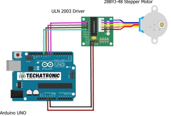
Firstly, let’s delve into the connections between the ULN 2003 driver module and the Arduino UNO.
Start by linking the 5-volt pin of the Arduino to the VCC (power) pin on the driver module. Connect the GND pin of the Arduino to the GND pin of the driver module. Proceed by establishing connections between the IN1, IN2, IN3, IN4 pins of the driver module and the digital-8, digital-9, digital-10, digital-11 pins of the Arduino, respectively.
Finally, interconnect the five pins of the stepper motor with the corresponding pins on the opposite side of the driver module.
Following these steps will prepare your circuit for operation.
Arduino stepper motor Code
// TECHATRONIC.COM
// CheapStepper Library
// https://github.com/tyhenry/CheapStepper
#include
CheapStepper stepper (8,9,10,11);
void setup()
{
stepper.setRpm(12);
}
void loop() {
stepper.moveDegreesCW (180); // you can set the angle
delay(2000);
stepper.moveDegreesCCW (160); // you can set the angle
delay(2000);
}
stepper motor with lcd 16×2
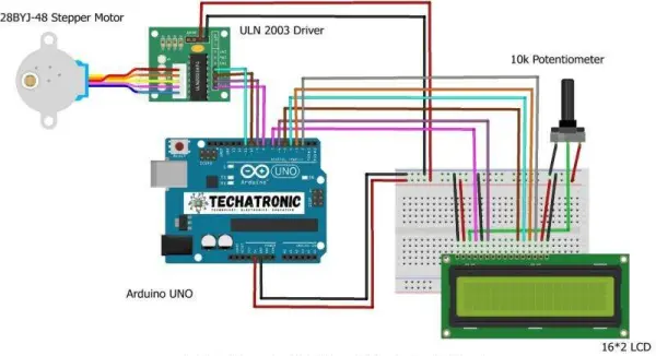
Establish the connections between the pins of the Arduino and the 16×2 LCD as illustrated in the provided diagram. To gain a better understanding of these connections, you can refer to our related article.
Commence by linking the 5-volt pin of the Arduino to the VCC pin of the driver module. Subsequently, establish a connection between the GND pin of the Arduino and the GND pin of the driver module. Proceed by interconnecting the IN1, IN2, IN3, IN4 pins of the driver module with the digital-8, digital-9, digital-10, digital-11 pins of the Arduino.
Finally, complete the setup by connecting the remaining pins of the stepper motor to the corresponding pins of the driver module.
stepper motor project Code
// TECHATRONIC.COM
// CheapStepper Library
// https://github.com/tyhenry/CheapStepper
#include “LiquidCrystal.h”
LiquidCrystal lcd(7,6,5,4,3,2);
#include
CheapStepper stepper (8,9,10,11);
void setup()
{
stepper.setRpm(12);
lcd.begin(16,2);
pinMode(12,OUTPUT);
pinMode(13,OUTPUT);
lcd.setCursor(0,0);
lcd.print(“TECHATRONIC.COM “);
delay(3000);
lcd.setCursor(0,0);
lcd.print(” Stepper Motor “);
}
void loop() {
lcd.setCursor(0,1);
lcd.print(“Clock Wise Directon “);
digitalWrite(13,HIGH);
digitalWrite(12,LOW);
stepper.moveDegreesCW (180); // you can set the angle
delay(2000);
lcd.setCursor(0,1);
lcd.print(“Anti-Clock Wise Directon “);
digitalWrite(13,LOW);
digitalWrite(12,HIGH);
stepper.moveDegreesCCW (250); // you can set the angle
delay(2000);
}
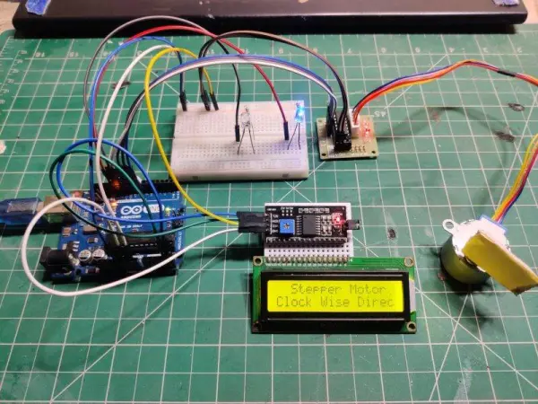
Circuit With 16×2 LCD And I2C Module
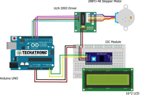
Next, link the 5-volt pin of the Arduino to the VCC pin of the driver module.
Connect the GND pin of the Arduino to the GND pin of the driver module.
Subsequently, establish connections between the IN1, IN2, IN3, IN4 pins of the driver module and the digital-8, digital-9, digital-10, digital-11 pins of the Arduino.
Connect the VCC and GND pins of the I2C module to the 5-volt and GND pins of the Arduino, respectively.
Finally, connect the pins of the servo motor to the driver module, and the SDA, SCL pins of the I2C module to the analog-4 and 5 pins of the Arduino. This setup simplifies the Arduino project involving a stepper motor.
Code
// TECHATRONIC.COM
// CheapStepper Library
// https://github.com/tyhenry/CheapStepper
// I2C LIBRARY
//https://github.com/fdebrabander/Arduino-LiquidCrystal-I2C-library
#include
#include LiquidCrystal_I2C lcd(0x3F,16,2);
// lcd(0x27,16,2);
#include
CheapStepper stepper (8,9,10,11);
void setup()
{
stepper.setRpm(12);
lcd.init(); // Arduino
lcd.backlight();
pinMode(12,OUTPUT);
pinMode(13,OUTPUT);
lcd.setCursor(0,0);
lcd.print(“TECHATRONIC.COM “);
delay(3000);
lcd.setCursor(0,0);
lcd.print(” Stepper Motor “);
}
void loop() {
lcd.setCursor(0,1);
lcd.print(“Clock Wise Directon “);
digitalWrite(13,HIGH);
digitalWrite(12,LOW);
stepper.moveDegreesCW (180); // you can set the angle
delay(2000);
lcd.setCursor(0,1);
lcd.print(“Anti-Clock Wise Directon “);
digitalWrite(13,LOW);
digitalWrite(12,HIGH);
stepper.moveDegreesCCW (250); // you can set the angle
delay(2000);
}
About the Code
Within this segment, we delve into the Arduino code pertaining to the stepper motor, elucidating the system’s functionality and the utilization of its inherent functions. Firstly, we incorporate a library to leverage its defined functions. Following this, we instantiate an object, specifically a stepper, and delineate the pins employed.
We designate digital pins 8, 9, 10, 11. In the setup function encompassing both the stepper and Arduino, we establish the motor’s revolutions per minute (RPM) utilizing the setRpm function. RPM denotes the motor’s rotational speed measured in rounds per minute. For demonstration purposes, we set it to 12, yet this value is adjustable to suit your preferences.
Within the loop function, we implement a predefined function to rotate the stepper motor in a clockwise direction to a specified angle. Subsequently, a delay ensues before rotating the stepper motor counterclockwise to a given angle. We trust that this explanation elucidates the code’s operation effectively.
Conclusion