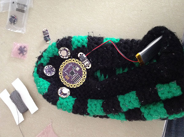
I made a little automatic slipper foot massager with the Lilypad Arduino and some of the Lilypad Vibe Boards for the actual massager. The sensor it uses is a Lilypad Accelerometer that I’m only using as a basic tilt sensor. Essentially it detects when the slipper is in a more vertical position (like when you would kick your feet up to relax) and then turns on the motors. When the slipper is in a more horizontal position (like when you’re walking), the motors turn off.
Read on for a parts list and guide on how to modify your own slippers (or shoes) to do the same thing.
Step 1: Parts List
The parts I used for this project are:
- 2 x Arduino Lilypad Main Board (I ordered the newer USB style from a shady dealer on ebay, but was sent the older mainboard style by mistake, but since they shipped from Hong Kong, and I was doing this for a class project, I couldn’t wait for the correct boards to be shipped. I should have ordered from SparkFun.com, they cost a little more than ebay, but they are fast shipping and I haven’t had an order messed up yet from them. Any arduino would work, even an UNO, but Lilypads are more conducive to e-textiles obviously. If you do get these older boards, make sure you have an FTDI board to program them, that’s another advantage to the newer boards that have the USB built into them, no need for extra programming boards).
- 2 x Lilypad Accelerometer Boards
- 2 x Lilypad Power Boards (I only had to order these since they sent the older boards and I had already ordered the lithium ion batteries from sparkfun that use the JST connectors. Newer lilypad boards have the connector built onto them, or you could use a different power supply if you wanted altogether).
- 4 x Lilypad Vibe Boards
- 2 x Lithium Ion Polymer Batteries (I used their medium sized ones, they have smaller and bigger, this seemed like a nice middle ground. Again, you can use any power source you prefer, these are just nice little rechargeable batteries, and the price is right on them. I wouldn’t use the smaller batteries as the vibe motors won’t last long on those, but they should last a good while on this size fully charged).
- ~5 feet of Conductive Thread (can’t tell you exactly how much you’ll need, but it didn’t take very much. All of the components are in a relatively small area, so you won’t need to sew long traces, so just a few feet of thread is all you’ll need. You could use wires, but the thread is much more comfortable on wearables).
- 2 x Slippers (I used some knit slippers called Pantoufles, pronounced “pawn-toof”, popular in Quebec, but any kind of slipper would work, or even shoes, heck you could sew it into a pair of socks if you really wanted to. Just need something that will be worn on your feet).
- You may also need access to a soldering iron, and possibly a multimeter for troubleshooting, but those items may not be required.
Step 2: Circuit Diagram
Here is my basic circuit design for this project. As you can see, I am only hooking up one axis on the accelerometer (the “X” axis). Since I am only using it as a simple tilt sensor, this was all that was needed. You could hook the “Y” and “Z” axis and really either get more precise tilt sensing (although the one access is sufficient) or you could have other crazy movements tracked to trigger the vibe boards. For this project though, we will only focus on using the single “X” axis.
In the circuit diagram, I have it laid out pretty close to how it goes on the slipper. You could change the placement of the vibe boards if you wanted it to focus it’s massage on different areas of the foot, but this is what worked for me. Also, if you have a newer lilypad board, the power board diagram will not be needed, you can just take that part out and use the on board battery jack.
Notice on the diagram how I have the board laid out. I did this for simplicity of getting to the pins I needed. In my code I am making extra ground and positive pins for the vibe motors and accelerometer, and we’ll discuss that later, but if you notice, the accelerometer is placed in a very specific way on the graphic diagram. There is a blank little pad that points up, I used that as my reference point, so when I was tracking the numbers and seeing what movements produced certain numbers in the serial monitor, I always held that pin forward (pointing toward the toes in the final slipper project) and started flat parallel to the floor. That was my “home” position. My code then is set to react if the sensor value hits above a certain number. This will be explained more in the coding section, but it’s good to note this when laying our your circuit especially with the accelerometer.
Step 3: Code
For the code, I took an existing sketch that far better coders created to gather the accelerometer sensor values and make them more usable. Essentially, they create 3 arrays for the “X”, “Y”, and “Z” axis values. The arrays take 8 values that the board spits out, and then divides those values by 8 (to get the average of the values), and then it spits that averaged value out. It smooths out the output and makes the data from the accelerometer much more usable.
I just added an “If” statement to say if the sensor value is greater than a certain threshold (with my setup it was 660), then turn the main board LED on and also the 2 massage vibe boards. I have uploaded this code so you can download it and change it to suit your hardware and preferences.
I’ll talk about prototyping in the next step where you can upload this code and then view the numbers your hardware is giving you and that way you can set the numbers to your liking.
Make sure and update the code with your own pins that you use on your board. Because I was just playing around with this code, I didn’t do the greatest job with naming variables etc… so you’ll have to search the whole code for pin changes.
 Pantoufle_Massager.ino
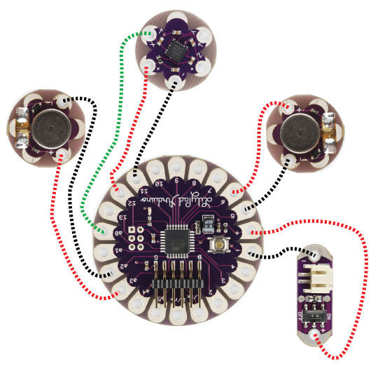
Step 4: Prototyping
Before you sew your circuit together on your slippers, it’s not a bad idea to grab some alligator clamps and test it out with your own hardware. Just hook it up following the wiring diagram, load in the code (making any pin changes that you may need based on your hardware), and then test out the function.
For more detail: Arduino Lilypad Slipper Automatic Foot Massager