Summary of Arduino GSM Communication: Calling and Messaging Tutorial
This article details an Arduino project using a SIM900 GSM module to make phone calls and send SMS messages via push buttons. The system uses two LEDs for status indication and monitors execution on the serial monitor. Users can trigger outgoing calls or texts by pressing specific buttons, with visual feedback provided by the LEDs turning on during operations.
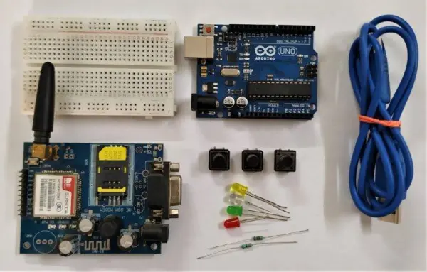
Parts used in the Arduino GSM Call and SMS Project:
- Arduino UNO
- SIM 900 GSM module
- Push buttons (pair)
- 220 ohm resistors
- Dual LEDs
- Jumper wires
- Breadboard
- USB cable
- 12-volt, 2-amp DC power supply
Introduction
Hello everyone, welcome back to our latest post. Are you familiar with a GSM module? In this article, we’ll explore making calls and sending messages using Arduino and the GSM module. If you’re new to understanding how a GSM module operates with Arduino, we recommend getting acquainted with it first. Ensure the connections are accurately set up, and then proceed to upload the provided code to your Arduino. Don’t forget to explore our other articles on Arduino and IoT that we’ve published.
Description
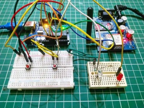
Within this Arduino GSM project, we’re equipped to initiate phone calls or send SMS using a GSM module.
Utilizing two push buttons, the first button allows you to initiate a phone call by providing the intended mobile number.
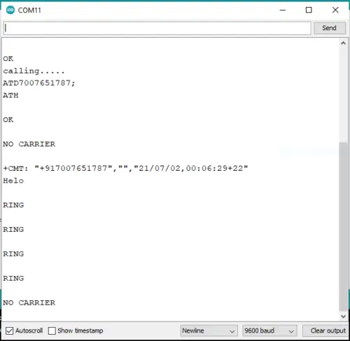
The execution status of the task can be monitored on the serial monitor screen.
An LED illuminates upon button press, signifying the ongoing task, and automatically switches off upon completion.
Additionally, explore our GSM-based forest fire alert system designed for digitalization.
Components Required in GSM project
Arduino UNO
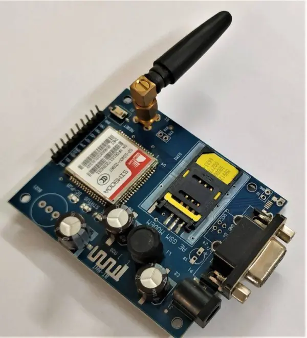
SIM 900 GSM module
A pair of push buttons
Resistors with a value of 220 ohms
Dual LEDs
Jumper wires along with a breadboard
USB cable utilized for code uploading
Arduino with GSM Module Circuit
| Arduino UNO | LED 1 | LED 2 | 220 Ohm Resistor |
| 4 Pin | Anode Terminal | ||
| 5 Pin | Anode Terminal | ||
| GND | Terminal 1 | ||
| Cathode Terminal | Cathode Terminal | Terminal 2 | |
| Arduino UNO | Button 1 | Button 2 | 220 Ohm Resistor |
| 7 Pin | Terminal 1 | ||
| 8 Pin | Terminal 1 | ||
| GND | Terminal 2 | Terminal 2 | Terminal 1 |
| Terminal 1 | Terminal 2 | ||
| Terminal 1 | Terminal 2 |
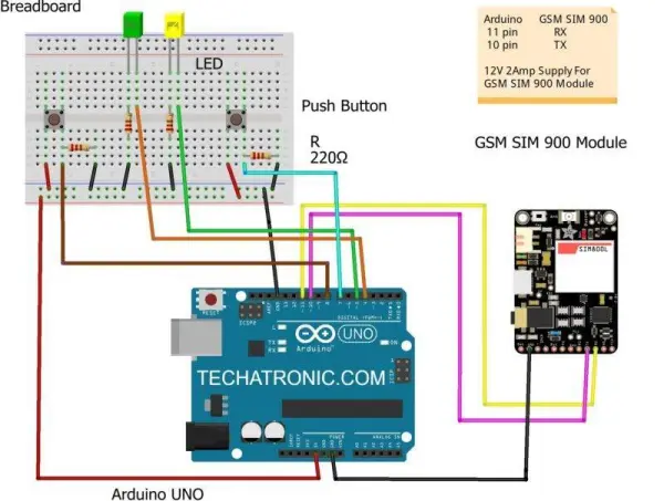
Link a 12-volt, 2-amp DC power supply to the GSM module.
Connect the Arduino’s digital pin 10 to the GSM module’s Tx pin.
Join the GND pin of the Arduino with the GSM module’s GND pin.
Attach the digital pin 11 of the Arduino to the Rx pin of the GSM module.
Next, connect the negative legs of two LEDs to the Arduino’s GND pin via a 220-ohm resistor.
Connect one LED’s positive leg to the Arduino’s digital pin 4 and the other LED’s positive leg to digital pin 5.
Take a push button and connect one of its pins to the Arduino’s 5V pin. Connect the other pin to the Arduino’s digital pin 8.
Repeat this step for the second push button, linking it to the Arduino’s digital pin 7.
Your circuit setup is now complete. Additionally, explore GSM-based Home Automation for more information.
Code for gsm and Arduino
// TECHATRONIC.COM
// Download Library of SoftwareSerial link given
// https://github.com/PaulStoffregen/SoftwareSerial
#include
SoftwareSerial gsm(10,11); // SoftSerial( RX , TX );
// 10 pin connect to TX of GSM SIM 900 Module
// 11 pin connect to RX of GSM SIM 900 Module
const int buttonPin1 = 7; // Push Button 1
const int buttonPin2 = 8; // Push Button 2
int buttonState1 = 0;
int buttonState2 = 0;
void setup()
{
delay(10000);
Serial.begin(9600);
gsm.begin(9600);
pinMode(buttonPin1, INPUT);
pinMode(buttonPin2, INPUT);
pinMode(5,OUTPUT); // LED1 pin D5
pinMode(4,OUTPUT); // LED2 pin D4
}
void loop()
{
buttonState1 = digitalRead(buttonPin1);
buttonState2 = digitalRead(buttonPin2);
if (Serial.available()>0)
switch(Serial.read())
{
case ‘r’:
RecieveMessage();
break;
}
if (gsm.available()>0)
Serial.write(gsm.read());
if (buttonState1 == HIGH)
{
gsm.println(“ATD7007651787;”); //replace x by your number
delay(100);
digitalWrite(5,HIGH); // LED1 ON
gsm.println(“ATH”);
delay(2000);
Serial.println(“calling…..”);
digitalWrite(5,LOW); // LED1 OFF
}
if (buttonState2 == HIGH)
{
Serial.println (“Sending Message”);
digitalWrite(4,HIGH); // LED2 ON
gsm.println(“AT+CMGF=1”); //Sets the GSM Module in Text Mode
delay(1000);
Serial.println (“Set SMS Number”);
gsm.println(“AT+CMGS=\”7007651787\”\r”); //Mobile phone number to send message, replace x by your number
delay(1000);
Serial.println (“Set SMS Content”);
gsm.println(“Techatronic.com”);// Messsage content
delay(100);
Serial.println (“Finish”);
gsm.println((char)26);// ASCII code of CTRL+Z
delay(1000);
Serial.println (“Message has been sent “);
digitalWrite(4,LOW); // LED2 ON
}
}
void RecieveMessage()
{
Serial.println (“gsm RECEIVE SMS”);
delay (1000);
gsm.println(“AT+CNMI=2,2,0,0,0”); // AT Command to receive a live SMS
delay(1000);
Serial.write (“Unread Message done”);
}
We trust you found this Arduino and GSM module project for calls and messages enjoyable and comprehended its functionality thoroughly. Should you encounter any uncertainties concerning this GSM project, please don’t hesitate to share your queries in the comments section below. Additionally, explore our collection of articles on Arduino and Raspberry Pi for more insights.
- How do I initiate a phone call?
Press the first push button connected to digital pin 7 to dial the number specified in the code. - Can I send an SMS message using this setup?
Yes, pressing the second push button connected to digital pin 8 triggers the sending of a predefined text message. - What indicates that a task is ongoing?
An LED illuminates upon button press to signify the ongoing task and switches off automatically upon completion. - Where can I monitor the execution status?
The execution status of the task can be monitored on the serial monitor screen. - Which pins connect the Arduino to the GSM module?
Arduino digital pin 10 connects to the GSM Tx pin, and digital pin 11 connects to the GSM Rx pin. - Does the system support receiving messages?
Yes, typing 'r' in the serial monitor initiates the reception of live SMS messages. - What power supply is required for the GSM module?
A 12-volt, 2-amp DC power supply must be linked to the GSM module. - How are the LEDs wired to the Arduino?
The negative legs connect to GND via 220-ohm resistors, while positive legs connect to digital pins 4 and 5.