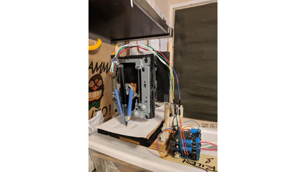
This project is based on mostly items which are easy to find. The idea is to take two unused computer disk units and combine them to create an automated drawing machine which resembles a CNC machine.
The pieces used out of the drives include the motors and railings from both of the drives and the plastic assembly of at least one of the drives (including tray)
Step 1: Requirements for Your Journey:
Pieces needed:
- Arduino uno
- 1 stepper motor (we used the model number 28BYJ-48)
- Adafruit motor shield v2
- Lots of wires
- Two computer cd trays
- optional: some 3d printed gears and rails
- Some wood or structural material A computer
Arduino Code Required:
- Custom GRBL code to work with Adafruit motor shield (Riley_adafruit_cnc_2)
Computer Software needed:
- Arduino IDE Plotter https://github.com/zapmaker/GrblHoming/releases
- Gcoded picture or drawing files (google your file of choice).
Tools needed:
- Soldering equipment
- Glue gun and glue sticks
- Ruler
- Pen
Step 2: Destruction

Take apart the dvd trays making sure to keep the structural integrity of at least one of the dvd trays while removing the metal component which usually has two railings. The process of taking these trays appart will vary from different cd trays. The two motor drives should look like the picture below once removed. Notice the part which spins the disk has been removed as it will not be needed.
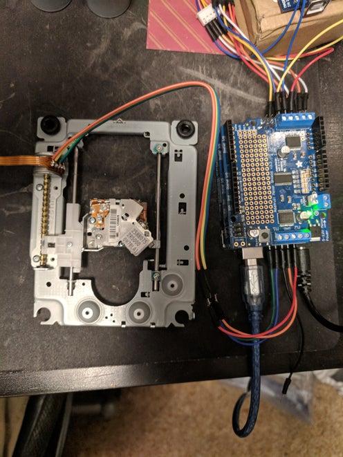
Step 3: Soldering On
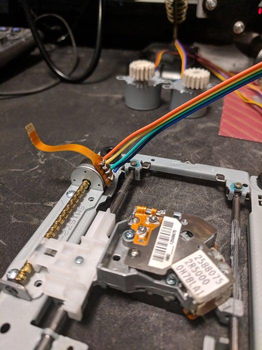
Once taken apart, the next step is to solder the terminals into the motor which may be seen in the picture. Again the way these terminals attach to the motor may differ according to the specific model. The way these connect to the Adafruit motor shield will be discussed later. Replicate the same setup for the second disk drive motor assembly.
These two will serve as our Y and Z axis in the drawing process.
Step 4: The Mighty Tray
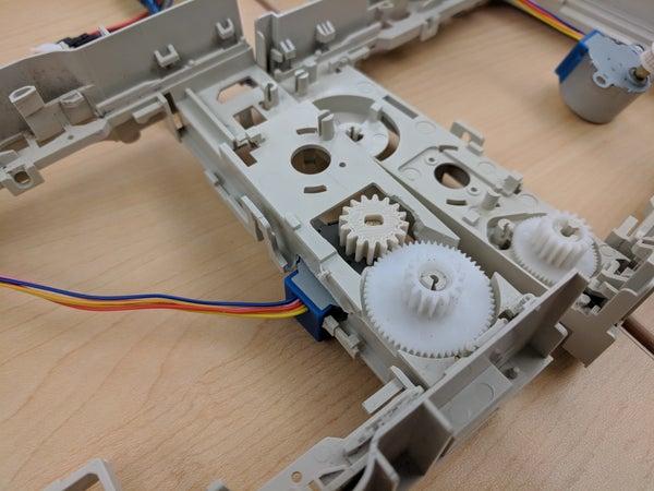
The next step is to get the disk tray working which will be the X-axis. For this purpose the stepper motor was used and the assembly required cutting parts of the tray to fit the gear through. (see pictures) At this point we realized our gear ratio was off and further tinkering was needed. At the end we opted to print a 4 to 1 ratio gear to allow for the smoothness and travel distance required to successfully complete the drawing without running out of room.
Step 5: The Arduino Affair
Put together the Arduino assembly and the motor shield setup. For this step a bit of soldering is needed. There will be two Adafruit Motor Shields stacked. Due to the way they operate a bridge needs to be soldered for the second arduino to be identified as such. The process behind that is explained here:
https://learn.adafruit.com/adafruit-motor-shield-v…
Solder the bridge as shown below labeled 1 for the top Adafruit motor shield. The first board should be (0x60) and the top board should be (0x61). Also, notice the jumper labeled 2. This is set on both the bottom and top shields telling the boards to draw their power from the arduino instead of the blue terminals right above it. You may choose to connect your own power source to these blue terminals if you find the arduino lacking. (Note, that while running the three motors we have the arduino connected to the computer plus a 9v power supply running to the arduino as well)
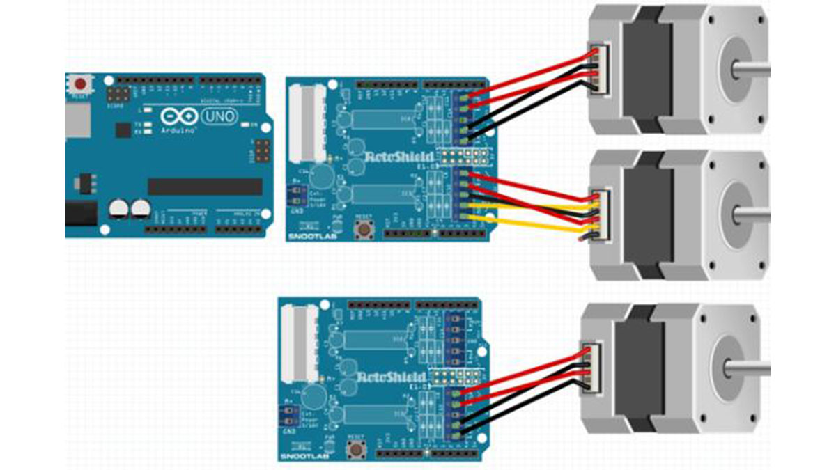
Step 6: Trial by Fire
Test! Before putting it all together test your parts. We found it particularly difficult to find information about how to connect stepper motors to the Adafruit Motor Shield. So here is a helpful diagram. It is important to point out that pin 1 and 4 (blue and orange) and pin 2 and 5 (pink and yellow) are pairs. Sometimes plugging these in the wrong way may mean a reverse in how the motor operates. Also, Red is ground in this diagram as shown below. If the disk assembly motors only have 4 terminals, leave the ground without connection.
To manage the movement of the motors use the software which was outlined in the required tools, using the plotter software in the link provided.
A really easy way to test which terminals are pairs is to test with a ohm-meter.
Here is a great guide on how to find your stepper motor wire pairs:
https://knowledge.ni.com/KnowledgeArticleDetails?i…
Once you found your pairs, put the first one into M1, the second into M2
Source: Arduino CNC Drawing Machine (or the Road to Success)