Summary of Arduino Cable Tracer
This article details the construction of an Arduino-based USB Cable Tracer capable of diagnosing cable integrity and wiring configurations for various USB types. The project utilizes an Arduino Mega 2560 to trace up to 48 wires simultaneously, displaying results on a 2.8" TFT LCD screen housed in a custom 3D-printed case. Users can identify broken connections, missing data lines, and charging-only cables by visually inspecting the tracer's output.
Parts used in the Arduino Cable Tracer:
- Arduino Mega 2560 board
- USB A to USB B Arduino Mega programming cable
- 2.8" TFT LCD display Touch ILI9341
- Vero Board (1 of 16x6 holes, 2 of 8x5 holes, 2 of 17x5 holes)
- Arduino dual strip male header pins (2 of 8 pins, 2 of 6 pins)
- Arduino Stackable Header (4 of 8 pins)
- Vero Pins (qty of 48)
- 2 x USB-C V3.0 Cable
- 2 x USB-C to USB-C through adapter
- 2 x USB Mini to USB A adapter
- 1 x USB Micro cable with socket
- 1 x USB-A cable with socket
- 1 x USB-A V3 cable with socket
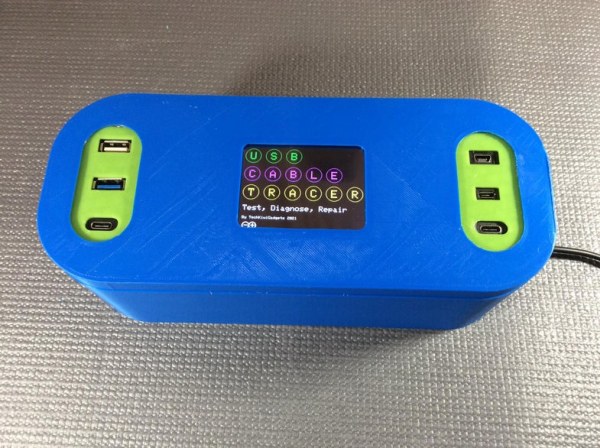
Instantly diagnose the type and integrity of USB cables with this Arduino Cable Tracer. Suitable to trace USB A, Mini, Mico, and USB-C cables this is very useful to identify the exact wiring configuration and also diagnose broken connections.
Step 1: Gather the Materials and Tools
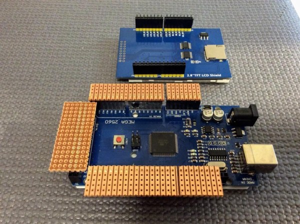
The Arduino Mega board is an excellent option for this project because it can support both a display and provide an additional 48 digital pins to simultaneously trace each of the wires within a cable. For this prototype, I used existing cables with commonly used USB sockets.
Parts list
- Arduino Mega 2560 board
- USB A to USB B Arduino Mega programming cable
- 2.8″ TFT LCD display Touch ILI9341
- Vero Board (1 of 16×6 holes, 2 of 8×5 holes, 2 of 17×5 holes – see photo)
- Arduino dual strip male header pins( 2 of 8 pins, 2 of 6 pins – see photo)
- Arduino Stackable Header 4 of 8 pins
- Vero Pins qty of 48
- 2 x USB-C V3.0 Cable
- 2 x USB-C to USB-C through adapter
- 2 x USB Mini to USB A adapter
- 1 x USB Micro cable with socket
- 1 x USB-A cable with socket
- 1 x USB-A V3 cable with socket
Tools
- Access to a 3D printer with a Build Plate of 220mm (i.e Creality Ender 3)
- Soldering Iron
- Box cutter knife
- Metal Ruler
- Wooden chopping board
- Heat Shrink insulation
- Wire Strippers
- Heat shrink air gun
- Hot Glue Gun
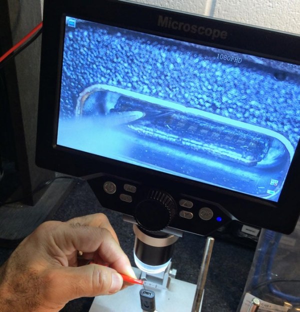
- Electronic PCB microscope (optional if you have issues with cable wiring)
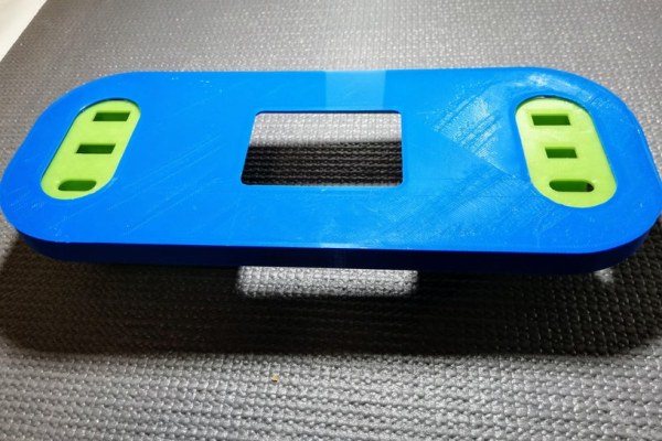
Step 2: Print and Assemble the Case
Printing the Components
The 3D Print files and printing instructions are included in a Thingiverse link here for the Lid, Base, left, and right USB socket bezel and a screen mounting bracket.
Cleanup the items
Once the components are printed remove any excess plastic paying particular attention to the mounting holes and also the base unit which has provision for external power to the unit.
Step 3: Prepare the PCB
1. Cut the Vero Board to size
Use a pencil to mark out the dimensions of each Vero board
- 1 of 16×6 holes
- 2 of 8×5 holes
- 2 of 17×5 holes
Ensure the orientation of the track is as described in the photo above.
Using a box cutter knife, metal ruler and a wooden chopping board carefully scour the correct size and carefully snap to the right size.
Cut a careful strip down the Vero with16x6 holes as indicated in the photo above. Use the blade of the box cutter to ensure there is no track between each hole.
2. Solder the Header pins
Carefully break the Arduino dual strip male header pins to fit in the Arduino Mega data sockets. Push the Vero boards into position with the track facing upwards. When satisfied solder the header pins into the Vero board.
3. Solder in the Vero Pins
Carefully push the Vero Pins into each of the Vero boards as indicated in the photo. You may need to use a small drill bit to widen the holes the pins are too tight.
Note that on the socket with dual header pins the Vero pins are spaced in a way to enable the wires to be soldered in with better clearance. See the photo above.
4. Mount the Stackable Header Sockets.
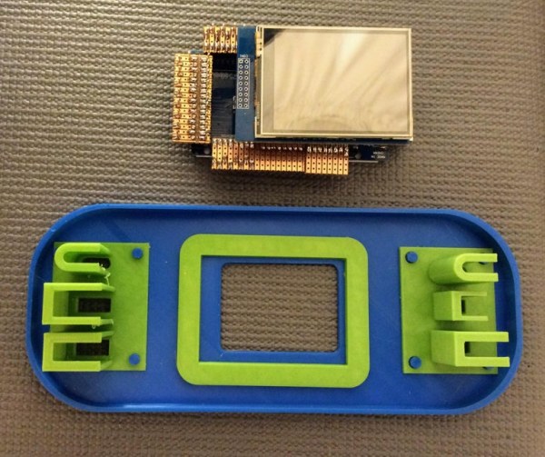
Push the stackable header pins onto the 2.8″ TFT LCD screen and use this to position the screen on the Vero board. Carefully solder the Stackable header sockets into place as indicated in the picture above.
5. Alignment of the Screen Mounting Bracket
Now is a good time to position the 2.8″ TFT LCD display in the Screen Mounting Bracket. This is best done with the screen turned on before you glue the screen mounting bracket into place. Take care to insert the Screen into the correct pins on the Arduino. When powered on you should be able to see the viewable area of the screen through the front panel. Once in the correct position, you can hot glue the screen mounting bracket into position however take care not to fasten the screen into place until all wiring is complete.
Step 4: Connect the USB Sockets to the Arduino Mega
1. Validate the cable configuration
I have provided a breakdown of color-coded wires to pin connections for the Arduino in a PDF document. Please note that some cables (particularly USB-C) may use different colors so in order to be certain it’s best to use a multimeter to test each connection to a pin to be sure of the config. It can be a little difficult to do this because of the USB-C cable turned out to have 16 wires and 24 pins.
Hopefully, you don’t have to do this and can follow my diagram above which shows which cable color is aligned. My suggestion is to try these and if there are issues use a multimeter.
If you do end up using a multimeter you will likely need to use a PCB microscope and a needle to strobe all of the pins in a USB C see photo above.
2. Cut and position the USB cables
Firstly using hot glue, position the USB sockets in the correct position. Then carefully position the Arduino and screen in the front panel and then put in place the USB cables. Cut the USB cables to the appropriate length so that they provide enough length to accommodate the position of the Arduino header pins.
3. Strip and Insulate Wires
Strip and insulate the cables with heat shrink so that any exposed shielding or earth wires are not exposed so as to avoid any short circuits occurring.
Strip and tin the ends of each of the wires carefully. You will find the USB-C wires will have aluminum foil shielding so remove this and use heat shrink to cover and hold them away from the chassis.
4. Connect wires to the Arduino
Carefully follow the wiring configuration table provided which shows the Arduino pin numbers, USB sockets and the associated pin numbers. Preload each connection with a piece of heat shrink so you can solder the joint and then slip heat shrink over the joint to hold and insulate the wire.
Do a final inspection with a microscope or magnifying glass and light up close to ensure there are no shorted terminals.
Step 5: Load and Test the Code
1. Load the Arduino Libraries
The standard GFX library does not support a 2.8 TFT screen however this can be addressed by a modified version provided here
Make sure this and other libraries are manually added to your Arduino IDE
- Adafruit_GFX
- Adafruit_TFTLCD
- TouchScreen
2. Upload and Test the code
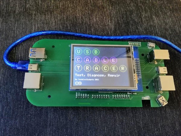
Upload the code via the Arduino IDE and on completion, you should see a color splash screen appear briefly on the LCD. The splash screen should clear and two arrows indicating port scanning are underway.
Step 6: Putting It All Together
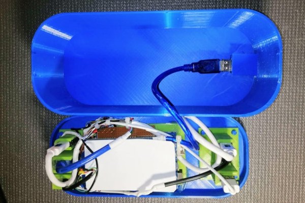
1. Install the Power Source
Carefully position the USB Mini adapter into the base of the case. Take the USB A to USB B Arduino programming cable and connector the USB mini adapter. You are now ready for testing.
2. Final Testing
Attach power to the USB Cabe Tracer and if working correctly the splash screen should clear giving way to the scanning screen as per the video demonstration above.
Take a USB A Micro cable and plug one end into the left of the unit and one on the right. Try various cables to test the cable connections. You should see wires identified as in the video.
3. Your USB Cable Tracer in Action
Take a series of USB cables and try them out.
Diagnosing Faulty Cables – A faulty cable compared to a working cable will show missing wires. In the example above you will see D+ and D- wires disconnect when the cable is flexed.
Identifying the right cable – Some cables are only used for fast charging, have limited or no data wires. These explain why some cables do not work on some devices. You can use the Cable Tracer to compare cables to identify the correct cables to avoid disappointment and frustration.
4. Feedback on this prototype
If you are interested in this project and have a preference for a different type of cable tracing then please message me with your feedback as I will consolidate this feedback and if there is enough interest produce a PCB header that will eliminate the soldering.
Thanks in advance
Step 7: Feedback on Prototype and Next Steps
I have received a large amount of feedback on what type of cables and connectors would be useful in a future model. So much that I have had a prototype PCB created that plugs directly into the Arduino Mega for testing and further development.
I have added in RJ45, USB B, USB Micro V3 and Lightning. If you have further suggestions please comment.
My intent would be to produce a board that others can experiment with different approaches to coding without having to do a lot of soldering to get results.
Thanks in advance and please continue with the feedback and will keep you updated on the availability of the PCB and new code to support it.
🙂
Source: Arduino Cable Tracer
- Why is the Arduino Mega board recommended for this project?
The Arduino Mega supports both a display and provides 48 digital pins to trace each wire within a cable simultaneously. - What libraries are required to run the code on the Arduino IDE?
You must manually add Adafruit_GFX, Adafruit_TFTLCD, and TouchScreen libraries, using a modified GFX version for the 2.8 TFT screen. - How can I verify the color-coded wire configuration for USB-C cables?
It is best to use a multimeter to test each connection to a pin because USB-C cables may use different colors and contain up to 16 wires. - What tools are necessary to prepare the Vero boards for the PCB?
You need a box cutter knife, metal ruler, and wooden chopping board to cut the boards to size and remove tracks between holes. - How do you prevent short circuits when working with exposed wires?
Strip and insulate the cables with heat shrink so that any exposed shielding or earth wires are not exposed. - What visual indicators show that the device is functioning correctly after uploading code?
A color splash screen appears briefly before clearing to show two arrows indicating that port scanning is underway. - How does the tracer help identify faulty cables?
A faulty cable will show missing wires on the display, such as D+ and D- wires disconnecting when the cable is flexed. - Can this device distinguish between data and charging-only cables?
Yes, it helps identify cables used only for fast charging that have limited or no data wires. - What future connector types are planned for the prototype PCB?
The developer has added RJ45, USB B, USB Micro V3, and Lightning connectors to a new prototype PCB.