Summary of Arduino-Based Smartphone-Controlled Light System
This article details a low-cost, phone-controlled lighting system using an Arduino Uno and Bluetooth module. It explains the circuit connections, provides the necessary code for data processing, and describes how the mobile app communicates with the microcontroller to toggle a relay and control an LED bulb. The guide emphasizes its versatility for IoT applications and suggests PCBWay for professional prototyping.
Parts used in the Phone-Controlled Lighting System:
- Arduino Uno
- Bluetooth HC-05
- 5v single channel Relay
- Led Bulb
- Some wires
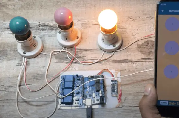
Hello everyone, welcome back to Techatronic. Currently, phone-controlled lighting has become quite prevalent and easily available in the market. However, today, we’ll demonstrate how to create a similar system at a significantly lower cost. This phone-controlled lighting setup is versatile and can be utilized anywhere by simply plugging it in and operating it via your mobile phone. An accompanying app will enable you to control the lighting seamlessly.
Introduction
The Android app-controlled light is a setup allowing you to manage a light bulb via a dedicated application. We’re designing this system with an LED bulb that the app can control. You can access the app for control through the provided download link. Alternatively, if you prefer creating the app yourself, our previous article, “WS2811 with Arduino Bluetooth control using Android app,” serves as a reference.
Additionally, this bulb can also be operated using a standard switchboard. Hence, we’ll establish the connections accordingly.
The phone-controlled light will link to the regular AC power supply. It’s a straightforward example of IoT (Internet of Things) and smart automation. Similarly, to controlling this light, you can manage various other devices such as motors, fans, AC units, coolers, depending on the AC load. The selection of a suitable relay depends on the load. To begin, download and install the app using the provided link.
Therefore, presented here is a comprehensive, step-by-step guide for creating a phone-controlled lamp. The initial phase involves familiarizing oneself with the components essential for this project.
Phone control Light Components Required
- Arduino Uno
- Bluetooth HC-05
- 5v single channel Relay
- Led Bulb
- Some wires
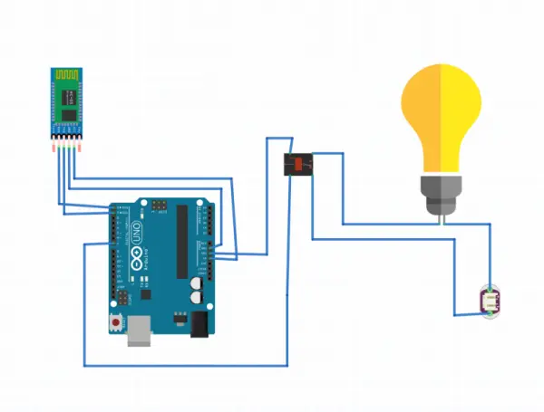
After knowing the components we have to connect them together in write manner so, we required a circuit diagram which can help us to connect all the components.
Circuit Diagram for Phone control light
Phone control light Arduino Code
void setup() {
// put your setup code here, to run once:
Serial.begin(9600);
pinMode(7, OUTPUT);
digitalWrite(7, HIGH);
}
void loop() {
// put your main code here, to run repeatedly:
if(Serial.available()>0)
{
char m= Serial.read();
if(m==’A’)
{
digitalWrite(7, HIGH);
}
else
{
digitalWrite(7, LOW);
}
}
}
This exemplifies the variety of home automation projects we’ve undertaken. If you’re interested in exploring further, we’ve provided links to different home automation projects below:
– WiFi-Based Home Automation with NodeMCU ESP8266
– Blynk Home Automation System
– IoT-Based Home Automation Project
– Home Automation Using Arduino and Bluetooth
– GSM-Based Home Automation Utilizing Arduino & SIM900
Each of these projects represents a distinct type of home automation system. You can select and create any of these based on your specific needs and preferences.
Working of Phone control Lamp
Upon launching the application and establishing a connection with the device, it signifies the successful pairing of the mobile phone’s Bluetooth with the Light Bluetooth device. This establishes a Bluetooth communication link between both devices, enabling the mobile phone to transmit data to the light. Essentially, the microcontroller, in this case, an Arduino, contains specific code facilitating this data exchange.
PCBWay PCB Prototyping Services
I’ve set up the entire circuit on a breadboard. However, considering that a breadboard setup isn’t optimal for this project, PCBWay provides rapid PCB prototyping for research purposes. Personally, I highly recommend PCBWay because they can deliver your initial boards within just 24 hours!
The prototyping phase stands as a crucial period for engineers, students, and hobbyists. PCBWay not only accelerates board production but also ensures accuracy and cost-effectiveness, significantly reducing both cost and development time for your electronic projects.
PCBWay offers a wide spectrum of PCBs, ranging from 2 Layer to advanced HDI and flex boards, each tailored to diverse functionalities and applications. I am thoroughly impressed by their board quality, prompt delivery, and cost-efficiency.
Imagine an app with two buttons; pressing the first button sends ‘A.’ Upon reception by the light system, a code triggers the light to turn on. Similarly, pressing the second button sends ‘B,’ prompting the system to process and turn off the light upon receiving ‘B’ in the data stream.
The Arduino device receives data via Bluetooth, paired with a phone’s Bluetooth connection. Subsequently, Arduino proceeds to verify and compare this received data with the information stored in its database. Upon evaluation, Arduino sends commands to activate the relay. Once triggered, the relay operates as an electronic switch, capable of being activated by a 5V voltage. In this setup, the relay effectively controls the on/off functionality of a light bulb. Essentially, Arduino manages the switching of the relay, thereby controlling the light’s activation and deactivation.
- How can I control the light via my mobile phone?
You can use a dedicated Android app to pair with the device's Bluetooth and send commands like 'A' or 'B' to turn the light on or off. - Can this system be operated without the app?
Yes, the bulb can also be operated using a standard switchboard alongside the phone control setup. - What is the best way to manage other AC devices like fans or motors?
You can manage various devices such as motors, fans, and AC units by selecting a suitable relay based on the specific AC load. - Does the Arduino code check for specific characters to operate the light?
Yes, the code checks if the received character is 'A' to turn the light on or anything else (like 'B') to turn it off. - How does the relay function in this project?
The relay acts as an electronic switch activated by 5V voltage from the Arduino to control the on/off functionality of the light bulb. - What should I do if I want a more permanent setup than a breadboard?
It is recommended to use PCBWay for rapid PCB prototyping to ensure accuracy, cost-effectiveness, and faster delivery. - Can I create my own app for this project?
Yes, you can refer to the previous article titled WS2811 with Arduino Bluetooth control using Android app to create your own application. - What happens when the app sends data to the Arduino?
The Arduino receives the data via Bluetooth, compares it with stored information, and then sends commands to activate the relay.