If you haven’t already, check out the Leader-Follower Robot project (https://www.instructables.com/Leader-Follower-Robot-Legs/). The Leader-Follower Robot project provides important background on the concepts covered in this tutorial. We will also be using the Leader-Follower Robot to showcase some cool sensors!
This Instructable will be a deeper dive into many of the sensors you can use to add utility to your Arduino projects. You should already be familiar with the potentiometer, as we used it in the last two projects. Through this is Instructable, we will explore some other sensors in your kit and complete a project that extends the follower leg to wave at passers-by!
Supplies
Components
Follower Leg
UNO R3 Super Starter Kit (or a comparable Arduino kit with sensors, breadboards, and jumper wires)
Software
Arduino IDE
Step 1: How an Arduino Uses a Sensor
There are many sensors that an Arduino can connect with to monitor and interact with things in its environment. In this tutorial, you will be introduced to a few common sensors included in most Arduino kits and implement one of your choice to expand on what you’ve learned so far. In previous tutorials, you’ve already learned how to control servo motors and how to use potentiometers as position sensors. In this module, you’ll be challenged to create a project that reacts to a sensor input.
If you are not familiar with Arduinos, check out the brief overview included in our Servo Creature Project (https://www.instructables.com/Servo-Creature/).
Sensors will interact with an Arduino through its pins. There are two types of pins the sensors can interact with:
Digital pins provide an input/output that is either High (5V) or Low (0V). Many sensor libraries (libraries are just pre-written code that you can import and use in your project) will use digital signals. Digital signals are basically a series of high and low pulses (think morse code) that can be used to communicate with sensor hardware.
Analog pins can read values on a scale from 0 to 5 volts. They can also output a value from 0 to 1023 which translates to a voltage between 0 and 5 volts. You have already seen how you can use analog signals to read the position of a potentiometer.
Step 2: Ultrasonic Sensor
The ultrasonic sensor is a sensor that uses high-frequency sound to measure distance. It sends out ultrasound at 40,000 hertz (higher than what a human can hear). If it bounces off of something in front of it, the sound will be reflected back to the sensor, which can detect the “echoed” reflection. By measuring the time between the emission and echo, the sensor can determine the distance to an object.
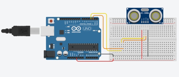
The ultrasonic sensor has 4 pins. Two provide power. One, the Trig pin, takes a pulse from the Arduino to indicate to the sensor to emit an ultrasonic pulse. The Echo pin provides an input to the Arduino which indicates the distance the sensor reads.
You can reference the circuit diagram above to connect the sensor to the Arduino. The sample code attached will print out how far something is from the front of the sensor through the serial monitor (Tools > Serial Monitor).
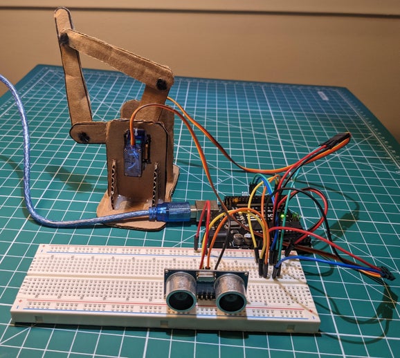
At the end of this tutorial, you will see how we use the ultrasonic sensor along with the follower leg to wave when someone passes by!
Step 3: Button
One of the most common sensors is the button. Your kit probably includes several “momentary” buttons, which are small black buttons with four pins. Buttons are basically switches that close (conduct) when they are pressed and open (stop conducting) when you stop pressing them. A button is an example of a sensor that would use a digital pin as it is either closed or open (High or Low).
If you look under your button, you will see that pins across the widest span of the button are connected. Electricity conducts between these pins when the button is pressed.
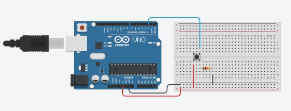
You can use the wiring diagram above to connect a button to the Arduino. You will notice that there are three wires that connect to the Arduino and a resistor (I used a 10k ohm resistor). This resistor is called a “pull down” resistor. This is because the resistor pulls down the voltage read by the Arduino to GND (0 volts) when the button is pressed. Without the pull down resistor, the Arduino would read a “floating” voltage – which is basically whatever random voltage the pins happens to be at. Floating voltages can be close to 0 volts, but can also sometimes be very high (20V+) due to static electricity. Reading a floating voltage will cause your Arduino to randomly think the button is getting pressed. The pull down resistor ensures that, when the button circuit is open, the Arduino is reading a reliable GND voltage.
The resistor is also important to prevent a “short circuit.” A short circuit is when a voltage source is connected directly to GND without powering a device. If someone has ever told you not to put a wire across the terminals of a battery, it’s because they don’t want you to short circuit the battery. Short circuiting will cause a lot of current to flow, producing a lots of heat and probably frying your Arduino. Thankfully, the Arduino can’t produce very much power so, if you short circuit it, it’s not dangerous. You’ll just have to buy a new Arduino. The resistor limits the amount of current that can flow through the button, preventing a short circuit.
To test out the button, you can load an example sketch by opening your Arduino IDE and going to File > Examples > Digital > Button in the top menu.
You can visit this link to learn more about buttons: https://www.arduino.cc/en/Tutorial/BuiltInExamples/Button
Step 4: Joystick
The joystick combines components of two sensors we have previously seen – the potentiometer and button. We already know how both of these sensors work, so we will just focus on how to connect the joystick to the Arduino.
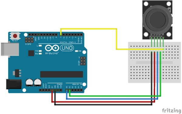
The joystick contains two potentiometers – one for the up and down directions and one for the side to side directions. If you push the joystick, you will press a button underneath the joystick knob.
There are 5 pins you will need to connect to use the joystick. Consistent with the diagram above, VCC should connect to 5V, GND to GND, VRx to A0, VRy to A1, and SW to Digital Pin 2.
Once you have this wired, you can download the attached sample sketch to print out readings from the joystick.
Step 5: Photoresistor
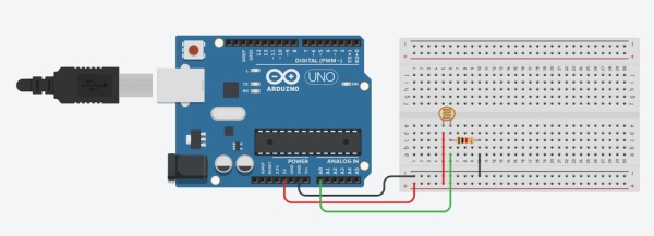
The next sensor we will cover is the photoresistor. The photoresistor is an analog sensor that acts like a variable resistor. As the light the sensor is exposed to increases, the resistance of the sensor decreases. We can use an analog input pin to read the voltage across a photoresistor, which is directly related to the resistance of the photoresistor.
You might notice that there is a second 10k ohm resistor in the circuit diagram above. This serves a different purpose than the resistor in the button circuit. Instead of being used as a pulldown resistor, this resistor forms a “voltage divider” with the photoresistor. We won’t go into too much detail about how a voltage divider works. All you need to know is that connecting the Arduino to the center of the voltage divider allows you to read the photoresistor sensor. If you want to learn more about voltage dividers, you can Google it!
To test the photoresistor, ensure your circuit is identical to the diagram above with the analog pin 0 connected. You can download an example sketch in your Arduino IDE from File > Examples > Analog > AnalogInSerialOut. This will print the analog input to the serial monitor (Tools > Serial Monitor). It will also write to a PWM pin, but you can ignore this portion of the code.
Step 6: Thermistor
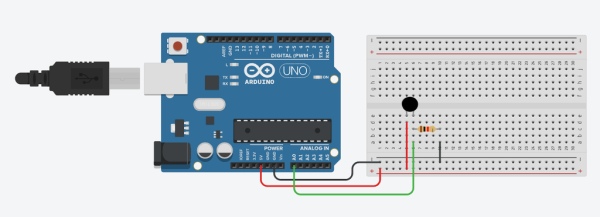
You can think of a thermistor very similarly to a photoresistor, but for temperature. As does the temperature changes, so does the resistance.
This will be wired up similarly to that of the photoresistor. Using the diagram above as a guide you will connect the analog input to analog input 0. Make sure you pay attention carefully to the given wiring diagram.
To test this, you can download an example sketch in your Arduino IDE from File > Examples > Analog > AnalogInSerialOut. This will print the analog input to the serial monitor (Tools > Serial Monitor). It will also write to a PWM pin, but you can ignore this portion of the code.
Step 7: Temperature and Humidity Module
The last sensor from your kit we will cover is the temperature and humidity sensor. You can imagine how this sensor could be used in a weather station project. Another idea is you could use it to attach to a fan to automatically turn on at a certain temperature. To expand on what you’ve learned so far, you could use the temperature and humidity sensor to move your follower leg.
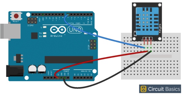
The temperature and humidity sensor is a digital sensor that is connected to a digital input pin and requires an Arduino code library to use.
The wiring for this sensor is very simple.
Looking at the module with the pins facing down and the blue portion towards you – the left most pin should connect to a digital pin, the middle pin should connect to 5V, and the right pin should connect to GND.
To read the values, you can download the included sample sketch. You will need to add a library to interpret the data from the module. You can do this by going to Sketch > Include Libraries > Manage Libraries. Search “DHTLib” and click the install button in the bottom right corner. Now you should be able to upload the sketch to the Arduino and read input in the serial monitor.
Step 8: Extend the Follower Leg
Now that we have explored sensors and how the Arduino can use them, we will use one of the sensors to extend the functionality of the follower leg built in the Leader Follower Robot Leg project. Check it out here (https://www.instructables.com/Leader-Follower-Robot-Legs/) if you have not already completed that project.
Step 9: Brainstorm an Idea
The first step in extending the Follower Leg is deciding what we want to do. Think about the types of things each sensor would allow. The ultrasonic can output distance measurements, the temperature and humidity sensor can give you information about the weather, the photoresistor can tell whether it’s exposed to light.
Once you have thought about the sensors you would like to use, you may also want to think about what the leg could do in response to that information. For example, the leg could be set to a certain position, it could wave, or it could move at a certain speed in response to a sensor reading. Instead of using the leg, you could also just control a servo and/or LEDs directly.
For this project, I chose to use the ultrasonic sensor to make the leg wave whenever someone moves by it.
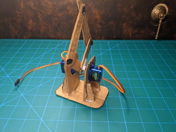
Step 10: Review of the Follower Leg
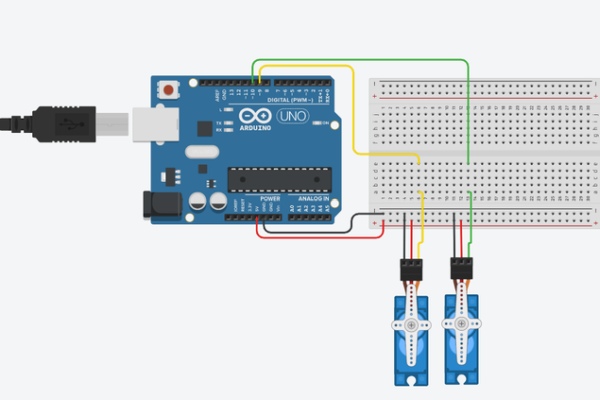
As a reminder, the Follower Leg is controlled by two servos. By changing the position each servo motor is set to, you can change the orientation of the leg.
The circuit diagram above shows how you would wire up the servo motors. The red wires are connected to the 5V pin of the Arduino and the brown wires are connected to the ground pin. The yellow wire is connected to a Digital PWM pin (pins 9 and 10 for the two servo motors).
You should be able to move the follower leg with code provided in the Leader-Follower project linked above.
Step 11: Connecting the Ultrasonic Sensor
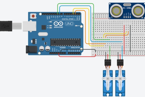
As a reminder, the ultrasonic sensor has 4 pins. The Vcc pin connects to the 5V Arduino pin, the Gnd pin connects to the GND pin on the Arduino, the Trig pin on the sensor connects to a Digital PWM pin on the Arduino (I will use pin 3), and the Echo pin on the sensor connects to a Digital pin on the Arduino (I will use pin 2). The circuit diagram above allows you to control two servos with input from the ultrasonic sensor.
Step 12: Test the Ultrasonic Sensor
With the ultrasonic sensor plugged in, you can use the Arduino sketch attached to test it out. Download the attached code and open it in your Arduino IDE. To see the values from the sensor, you should open the serial monitor from Tools > Serial Monitor in the top bar.
When you compile and upload the sketch to the Arduino board it will start printing distance values out. That is the distance of whatever is directly in front of the sensor.
Step 13: Code the Leg Movement
Our goal will be to use the ultrasonic sensor to detect when somebody walks by so the follower leg can wave at them. We will break this down into two main tasks: 1) detecting when someone walks by and 2) controlling the servos to make the leg wave at them. We will first write some code to make the leg wave.
We will make the leg wave using “functions.” Functions are code blocks that can be used to complete a specific task. You can call a function in your code whenever you want to accomplish that task. In a nutshell, functions are basically a compact way to copy and paste code blocks that you commonly use. For example, if you frequently want to make an LED flash three times, instead of copy and pasting the code to do this over and over again in your Arduino project, you could write an LED flash function that can be called every time you want to flash your LEDs. I am going to make a wave function, that I can call whenever I want the leg to wave.
Although functions may sound confusing at first, you’ve actually been using functions all along! The setup and loop portions of every Arduino sketch are functions.
To make a function you will first make a “function header.” In this case it would be void wave(). The first word in a function header is what the function will return. For example, int sum() might return the integer sum of some numbers. The “void” keyword means that our function will not return anything. “Wave” is the function name. Lastly, the parentheses are used to provide input to the function. If the function was two add two values and return the sum, you may have the two inputs in the parentheses. We do not need any inputs for our task. All of the code to be executed when you call the function is enclosed in brackets {}.
As an example, whenever the sensor detects something closer than 10 cm, it could call this function.
Step 14: Detect Someone Walk by
While we could write some very simple code that just waves the leg whenever someone is closer than a certain distance, let’s make our project a little fancier by only waving when an object is getting closer to the leg. This is a more realistic behavior because people normally only wave once when somebody approaches. If we continued to wave as long as somebody was standing close to us, it would be pretty hard to make conversation!
The code attached is structured so the leg will wave as soon as somebody gets closer than a certain distance threshold. If the object continues to get closer to the ultrasonic sensor, the leg will keep waving. Otherwise, the leg will stop. You can experiment with changing the code to get different behaviors!
You can download and test out the code from the attached file. You may need to change the start and end servo positions to be the same as what you used in the Leader-Follower project.
Step 15: Have Fun Waving at Everyone!

That is it for this project! I hope you had some fun tinkering with different sensors!
Most importantly, I hope this introduction to sensors will help you make more fun and complex builds!
Source: Smart Product Project – Intro to Sensors (Lesson 3)