Summary of 4x4x4 interactive LED-cube with Arduino
This article details the construction of a 4x4x4 interactive LED cube using an Arduino. The project utilizes a multiplexing technique to control 64 LEDs with only 8 pins. Key features include top corner LEDs acting as light sensors to trigger different visual shows based on ambient light levels. The guide covers tools, parts, and step-by-step assembly instructions for creating the grid structure and wiring the components.
Parts used in the 4x4x4 Interactive LED Cube:
- 64 LEDs
- 4 resistors
- 1 Photocube
- 1 Arduino
- Soldering iron
- Pliers
- Small screwdriver
- Drillbits and drill
- Solder
- Piece of wood
- Pencil and ruler
- Computer with Arduino software
- USB cable
- Snips
- Sharpie
- Breadboard (optional)
- Wire
- Small COAX wire (isolated wire)
- 16 headerpins
To explain my 4x4x4 interactive LED-cube published before, a bit more clear, I will try to make my first step by step instructable.
This 4x4x4 cube is interactive by using the top four corner LEDs both as LEDs and as sensors that will react on light. Depending on what LED gets the least light, the cube will run a different show.

Step 1: You will need:
TOOLS
soldering iron
pliers
small screwdriver
some drillbits
drill
solder
piece of wood
pencil
ruler
computer with Arduino software
USB-cable
snips
sharpie
breadboard (optional)
PARTS
64 led’s
4 resistors that go with the LED’s (yes just 4)
1 Photocube
1 Arduino
some wire
some small COAX wire (isolated wire)
16 headerpins
Step 2: Making the rig
Draw on a piece of wood a grid with the lines 12,5 mm apart. (12 or 13 or whatever will also do, but I did 12,5) Draw at least 4 lines horizontally and 4 lines vertically. (I did more, because you’ll never know what plans I will have in the future) You will now have 16 crossings. Drill some 5 mm holes (if your LEDs are 5 mm) at the crossings of the lines. If you first drill small holes, the location of your holes will probably be more exact.
This plank with 16 holes will be the rig for your soldering.
Step 3: Bending the legs of the LEDs
First I bended the legs of 16 LED’s. Hold the led upside-down diagonally, with the short leg in the upper left and the long leg in the lower right. Bend the cathode (short leg) to the left and the anode (long leg) down. So the flat part on the side of the LED wil be in the upper-left corner (the film and pictures will make this more clear I hope).
You can also bend 32 LEDs already if you are on a roll.
Step 4: Placing the LEDs in the rig
When at least 16 LEDs have bended legs (leads), you can place them in your rig. You will have 4 rows of long legs (anode) touching each other and 4 rows of short legs (cathode) touching. On some places, the anodes will also touch the cathodes when they cross each other. That is not a problem. We will solve that later.
Step 5: Soldering the first grid
Where the anode from one LED touches the anode from an other LED we will solder them together. Make sure that you don’t solder an anode to an cathode.
At the places where the anodes are crossing the cathodes, we want to make sure that the legs aren’d touching. (they probably are touching now) We do this by forcing some room between the anodes and cathodes with the use of a small screwdriver. Be sure that you make enough room, but also be careful enough not to break anything.
Step 6: Start playing
Sure you can work on until you are all the way finished, but isn’t it much more fun to first start playing with your just creates 4×4 LED-grid?!
So place your anodes in a breadboard an run some resistors from each of your cathode-rows to some free lanes in your breadboard. (they must be the value that you will need to light one LED from the 5V of your Arduino. This could be something like 560 ohm)
Next run 4 wires from the anodes in your breadboard to ports 4 till 7 on the Arduino and 4 wires from the resistors in your breadboard to ports 0 till 3 on the Arduino. To make this already interactive you will place a LED with the anode (long leg) in analog-port 0 and the cathode in GND of the Arduino.
Next you run the following code (sketch) on the Arduino and when you go with your hand over the LED in the analog-port of the Arduino, you will see the lights of your LED-grid light up.
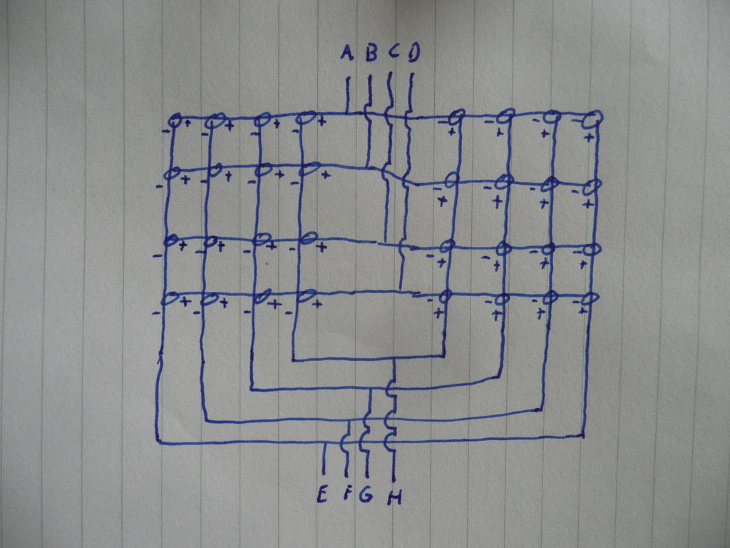
If it worked: yeah, you just multiplexed 16 LEDs. This means that you lighted up 16 LEDs individually by just using 8 Arduino ports, just by gritting them. We made just 4 anodes and 4 cathodes and with these 8 wires we can address 16 locations on the grid.
4 resistors that go with the LED’s (yes just 4)
1 Photocube
1 Arduino
For more detail: 4x4x4 interactive LED-cube with Arduino
- How does the cube determine which show to run?
The cube uses the top four corner LEDs as sensors that react to light; the specific show depends on which LED receives the least light. - What is the purpose of bending the LED legs?
Bending the legs allows the anodes and cathodes to be arranged in rows where they touch each other to form a grid for multiplexing. - How many Arduino ports are needed to address 16 locations?
Only 8 Arduino ports are required to address 16 individual locations on the grid by using 4 anodes and 4 cathodes. - What resistor value is suggested for the breadboard setup?
A value such as 560 ohm is suggested to ensure one LED lights up from the 5V output of the Arduino. - Why should you drill small holes first before drilling the final size?
Drilling smaller holes initially helps ensure the location of the final 5 mm holes is more exact. - Can the project be tested before finishing the entire build?
Yes, you can start playing with just the created 4x4 LED grid while continuing to work on the rest of the project. - Which Arduino ports are used for the anodes in the initial test?
Ports 4 through 7 on the Arduino are used for the anodes during the testing phase. - How are the cathode-rows connected in the breadboard test?
Resistors are run from each cathode-row to free lanes in the breadboard, connecting to Arduino ports 0 through 3.