Hello everyone !
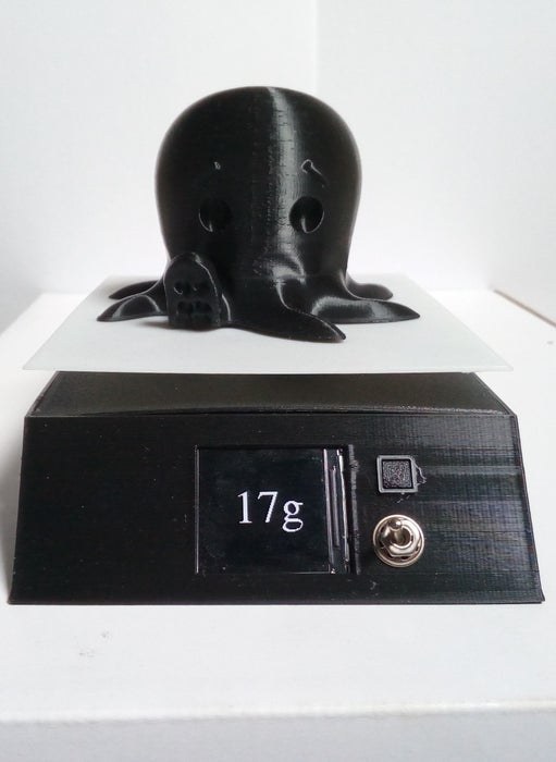
Today I’m going to show you how I built this little kitchen scale during this lockdown !
It can measure weights up to several kilograms, has an included battery, a nice display and can even be turned into a connected scale thanks to the the ESP8266.
I used a 20Kg load cell, because that was what I had at the time, but a 1, 2 or 5 Kg one would be better suited for this application, because they are more precise.
It doesn’t require a lot of skill, just basic soldering, and a little bit of experience with electronics is a plus.
Let’s start with what you’ll need !
Supplies
– A Load cell with an HX711 ADC (AliExpress)
– M4 and M5 screws
– An ESP8266 Board (AliExpress)
– A 10k 1206 resistor (optionnal)
– A 10k resistor
– A push button
– An On/Off switch
– A 1.3″ LCD Screen (AliExpress)
– A TP4056 Li-Ion charger board with output protection (AliExpress)
– A 3.7V to 5V boost converter (AliExpress)
– A Li-Ion battery (I used an 18650)
You’ll also need
– A soldering Iron
– A hot glue gun
– Access to a 3D printer
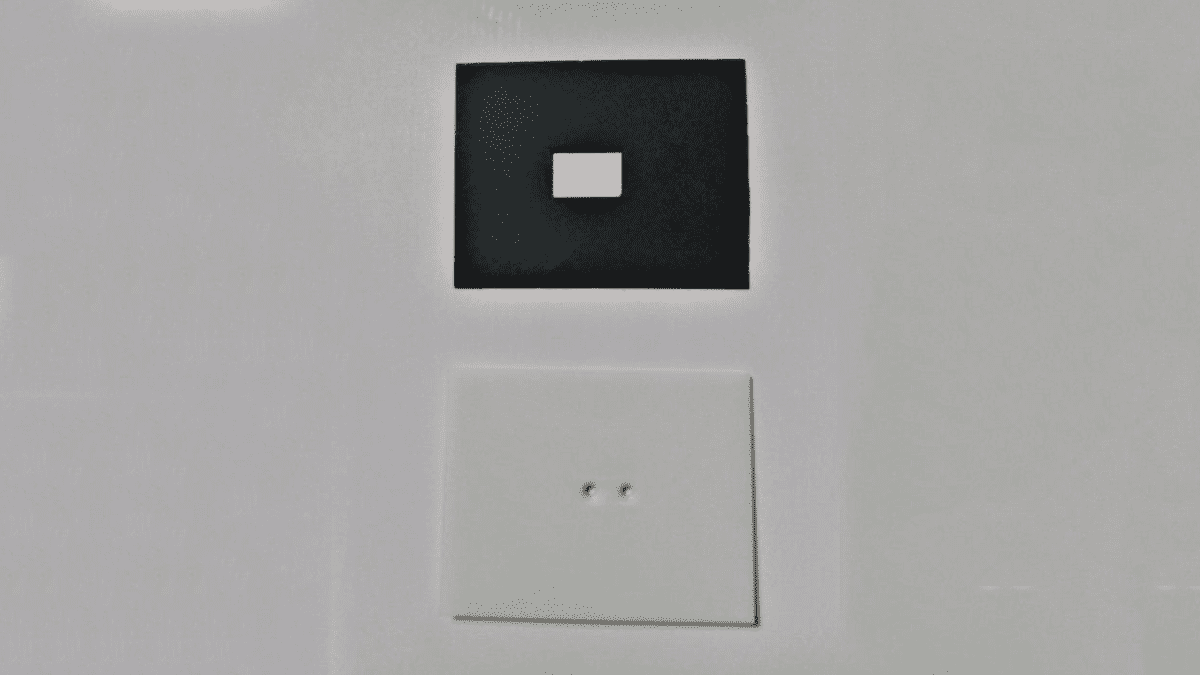
Step 1: 3D Printing the Parts
You can download the model on Thingiverse.
It is made up of 6 pieces :
- – Mainframe and Cover make up the main body of the scale
- – Plateau is where you put the thing to weight
- – Height fix goes between the plateau and the load cell
- – Button and Button Holder are used to create the tare button
I used black and white PLA on my Ender 3 Pro.
You can expect the whole printing process to take about 10 hours. I didn’t need support for the mainframe, bridging worked just fine.
There is a sacrificial layer on the mainframe, where the holes for the bolts are. You will need to remove it, with a screwdriver for example.
Step 2: Electronics
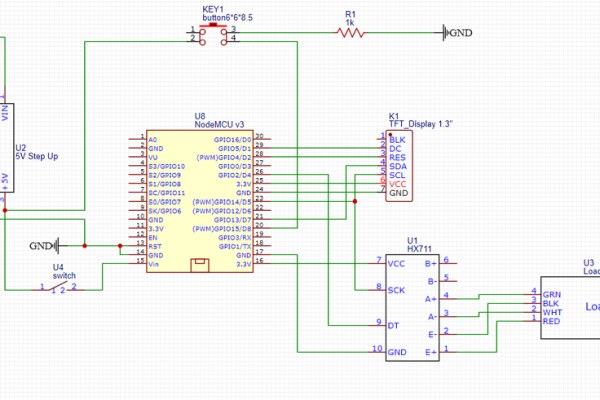
You need to solder the components according to the schematic. I did not create a PCB to use less room, and because it was cheaper. This makes soldering harder but it still is possible. Just take your time double check every time before soldering.
Depending on the micro-controller that you want to use, you may need to modify the HX711 by following this tutorial.
Step 3: Assembly
First, attach the load cell to the mainframe using two M5 bolts and nuts. Then, using a hot glue gun, glue the screen to the mainframe, the orientation doesn’t matter as you can modify it later in software. Screw the main switch to its hole. Glue the push button to its hole and the step up converter next to its port, and the shove the rest in the mainframe.
Use a bit of hot glue to make sure that everything stays in place.
Then, with some cyanoacrylate glue, stick the button holder to the mainframe, and the button cover to the push button.
The assembly is almost done, but before we can continue, we need to program the ESP8266.
Step 4: Programming and Calibration
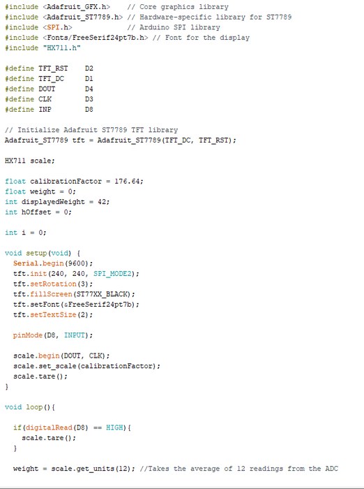
Simply upload this sketch to the ESP8266 using the Arduino IDE :
// Copyright (C) 2020  Cyril THOMAS
//
// This program is free software; you can redistribute it and/or
// modify it under the terms of the GNU Library General Public
// License as published by the Free Software Foundation; either
// version 3 of the License, or (at your option) any later version.
//
// This program is distributed in the hope that it will be useful,
// but WITHOUT ANY WARRANTY; without even the implied warranty of
// MERCHANTABILITY or FITNESS FOR A PARTICULAR PURPOSE.  See the GNU
// Library General Public License for more details.
//
// You should have received a copy of the GNU Library General Public
// License along with this library; if not, see .

#include  <Adafruit_GFX.h> // Core graphics library
#include  <Adafruit_ST7789.h> // Hardware-specific library for ST7789
#include  <SPI.h> // Arduino SPI library
#include  <Fonts/FreeSerif24pt7b.h> // Font for the display
#include "HX711.h"

#define TFT_RST    D2
#define TFT_DC     D1
#define DOUT       D4
#define CLK        D3
#define INP        D8

// Initialize Adafruit ST7789 TFT library
Adafruit_ST7789 tft = Adafruit_ST7789(TFT_DC, TFT_RST);

HX711 scale;

float calibrationFactor = 176.64;
float weight = 0;
int displayedWeight = 42;
int hOffset = 0;

int i = 0;

void setup(void) {
  Serial.begin(9600);
  tft.init(240, 240, SPI_MODE2);
  tft.setRotation(3);
  tft.fillScreen(ST77XX_BLACK);
  tft.setFont(&FreeSerif24pt7b);
  tft.setTextSize(2);

  pinMode(D8, INPUT);

 scale.begin(DOUT, CLK);
  scale.set_scale(calibrationFactor);
  scale.tare();
}

void loop(){

  if(digitalRead(D8) == HIGH){
    scale.tare();
  }

  weight = scale.get_units(12); //Takes the average of 12 readings from the ADC

  if((int)weight != displayedWeight){
    displayedWeight = (int)weight;

    if(displayedWeight < -100){ //To set the horizontal offset for the screen
      hOffset = 0;
    }else if(displayedWeight < -10){
      hOffset = 30;
    }else if(displayedWeight < 0){
      hOffset = 60;
    }else if(displayedWeight < 10){
      hOffset = 84;
    }else if(displayedWeight < 100){
      hOffset = 60;
    }else{
      hOffset = 30;
    }

    tft.fillRect(0,80,240,90,ST77XX_BLACK);
    tft.setCursor(hOffset,145);
    tft.print(displayedWeight);
    tft.print("g");
  }
}
We are using bogde’s HX711 library to communicate to the ADC, and the AdaFruit GFX and ST7789 libraries to communicate with the screen.
The code is pretty simple, so I won’t go into details about it. Notice the calibrationFactor variable. This is the variable that is used to convert the ADC readings to the corresponding weight.
To calibrate the scale, turn it on and put an object of known weight on the load scale. You can temporarily attach the plate if that helps. Look at the reading.
The calibation factor you shoud use is : currentFactor*(real weight / displayed weight)
Once the scale is calibrated, you are ready to finish.
Step 5: Finish

Once everything works, put the cover on the mainframe, glue it using superglue, and screw the plate using the two M4 bolts.
You should now be ready to use this kitchen scale.
I didnt’ have any use for making it connected, but you could easily make an IoT scale using the ESP8266 capabilities.
I hope this was useful, and thank you for reading this tutorial.
Cheers 🙂