DIY wattmeter with an Arduino
It is difficult or sometimes even impossible to measure power and energy with ordinary multimeters. To carry out such a measurement reliable and accurate, a special wattmeter is required. Because these meters are very expensive, a cheaper solution is presented here as a DIY wattmeter based on a Arduino Nano board.
Parameters
This wattmeter measures the real power, apparent power, reactive power, phase and energy. Beside that, the wattmeter measures also the mean, RMS, standard deviation, maximum, minimum and frequency of both the voltage and current. And it can measure the area of the voltage (flux) and current (charge) and keeps track of the measure time. Depending on the used display two or four parameter can be read simultaneous.
As an ideally instrument should do; it makes no distinction between AC or DC. It all boils down by choosing the right parameter which all are mathematically justified calculated. The bandwidth is approximately 1.8 kHz for the voltage, current, real and apparent power. The bandwidth for reactive power and phase is limited to 50~60 Hz mains frequencies.
Accuracy
Considering that an Arduino isn’t the most accurate board, still a reasonable measurement instrument can be made with it. When the prescribed components are used and after calibration an accuracy of 0.2 % over a temperature range of 10 °C can be achieved.
Code
The Arduino code for this wattmeter is available as a text file: arduino-wattmeter-code-v1.0.
Circuit
To keep the circuit and construction as simple as possible, one sacrifice had to be made: The meter has fixed ranges for the voltage and current inputs. On the other hand, only a single amplifier is used, this to keep the burden voltage of the current measurement as low as possible.
General description
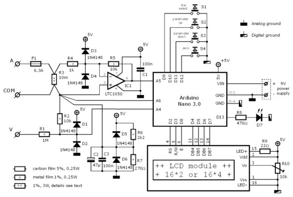
The voltage is measured between the “COM” and “V” terminal. A voltage divider R1 and R2 reduces this voltage so it can be measured with the analog input A4 of the Arduino. The diodes D1, D2 protect the Arduino against overvoltages. The current to be measured flows from the “A” terminal through the fuse F1 and the shunt resistor R3 to the “COM” terminal. The current through R3 causes a voltage drop across it that is proportional to the current. Because this voltage is very small (±50 mV full range) it is amplified by IC1 with R4,5 before providing it to a analog input A5. The diodes D3,4 protect the electronics against voltage spikes.
In order to make it possible to measure positive as well as negative voltages, the “COM” voltage must lie at half the reference voltage. The used internal Arduino reference voltage is 1.1 V, so the “COM” voltage must be approximately 0.55 V. The impedance of this voltage must be reasonably low compared to R2. Because the Arduino reference voltage can handle only small loads, the half reference voltage is derived from the 5 V power supply with the voltage divider R6 & R7. This voltage may vary over time but will not influence the accuracy because it is also measured (input A6) and used in the calculations.
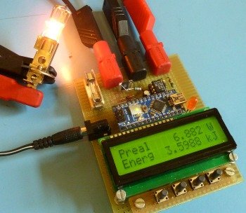
The measured parameters can be read from the 16*2 (or 16*4) character LCD-module that is connected by a 4 bit databus and 3 control signals to the Arduino. These parameters are selected by the four switches S1…4. The LED D7 is a overflow indicator and will light up if the voltage or current input is overloaded and the measurement isn’t accurate anymore. The wattmeter is powered by a 9 VDC adapter connected to the Arduino VIN and GND. The current draw is approximately 75 mA.
Voltage & current range
The voltage and current ranges are fixed and therefore the input circuitries must be adapted to the application wherein the wattmeter is used. When choosing a range, anticipate to higher peak values rather than the nominal value. For instance: when the wattmeter is used for a 12 V PV-system, the battery voltage can reach over 14 V and the open terminal voltage of a PV-panel could be high as 18 V. For the current values this could become much worse due to inrush currents. Keep in mind that the selected range concerns peak values. The peak value of a 100 Veff sinusoidal alternating voltage will be √2 higher: 141 V.
Voltage input attenuator
The voltage input attenuator is determined by the resistors R1 and R2. This resistor network will divide the input voltage so that the Arduino measures half reference voltage, 0.55 V, at maximum range. The resistor R2 has a fixed value of 10 kΩ, and the range is set by R1 and is calculated as:
![]() [Ω].
[Ω].
If for instance a 50 V range is required, R1 must be 899 kΩ. Because this value isn’t a standard value, the closest higher E12 value is 1 MΩ. The value for R1 is may never be chosen lower than 10 kΩ to retain the overvoltage protection. Therefore the lowest possible range is ±1.1 V.
Current range
The current range is determined by the resistive value of the shunt R3, the amplification and the analog input sensitivity. Because the Arduino input sensitivity is fixed at ±0.55 V and the amplification is also fixed at 10 times, the voltage drop across R3 at full range is ±55 mV. So the range is set by the value of R3 and can be calculated as:
![]() [Ω]
[Ω]
If a 5 A range is required, R3 must be 0.011 Ω, and is rounded to 0.01 Ω.
Shunt resistor properties
The shunt resistor is a critical component and needs some special attention. The resistive value of resistors are subject to temperature changes. Not only by the ambient temperature, but also by self heating. To reduce the self heating of the shunt resistor, the allowable power dissipation must be quite overdimensioned. The specified power dissipation must be approximately 10 times higher than the real maximum dissipation. In the given circuit the shunt resistor dissipates 5 A · 50 mV = 0.25 W, so a 3 W type is suitable. If the shunt resistor has a temperature coefficient of 50 ppm/°C than a tolerance of 0.1% is feasible within a 20 °C temperature range. This is including the self heating of the shunt resistor and the temperature rise within the instrument casing. If a shunt resistor is used with a higher temperature coefficient it will become dominant. The initial tolerance is of less importance: this is compensated by the calibration.
The burden voltage across the shunt is chosen very small (50 mV max.), therefore the resolution is 50 μV at a four digit display. The consequence of this is that thermoelectric voltages at junctions with different metals become noticeable if there are temperature differences between both terminals. These temperature differences can easily occur due to different power dissipations of components surrounding the shunt. Even small differences in the solder joints on the shunt resistor can cause temperature differences. Most resistors generate significant thermoelectric voltages and are useless in this application. The advised resistor for the shunt is the VISHAY-DALE – WSL3637R0100FEA who has excellent properties.
Amplifier
The LTC1050 is a special rail-to-rail opamp with a low input offset voltage (5 μV) and a low input bias current (10 pA). Don’t replace the opamp with any other type with unknown or worse specification.
Components analog section
All the resistors used in the analog section, R1, 2 and 4…7, are 0.25 W metal film types with a tolerance of 1 % and a temperature coefficient of 100 ppm/°C or better. The protection diodes D1…6 must have a very low reverse leakage current. However the specified 1N4184 isn’t the most suitable type, it normally performs well. There is a fairly large spread in the reverse leakage current, therefore it is advisable to measure this leakage current. To do so, connect the diode in reverse direction in a series circuit with a voltmeter (Ri=10MΩ) and a 9 V battery. The voltage measured may not exceed 100 mV, what corresponds to 10 nA leakage current.
Build
The wattmeter prototype shown in this article is build as a single PCB-unit to avoid external wirering to connectors. Only the fixed mounted riser board for the four push button switches is a kind of exception. It can be build on a Perfboard 80*100 mm large and is straight forward. Only the following needs special attention:
The current is measured by a four point measurement to the shunt resistor R3. The resistor has four terminals for that reason: I+ & I- wherethrough the current flows, and S+ & S- whereof the burden voltage is sensed. this is shown in the photo beside. Observe the star point connection in the circuit diagram at the sense terminal S- on the “COM” side. All the connections to this artificial “null” may only be made at this point to avoid measurement errors. The last thing is the distinction between the digital ground used for the switches and display, and the analog ground used for the analog input circuit. Don’t connect these two grounds together, the Arduino has an internal connection between these two grounds.
After soldering clean the circuit board and also the Arduino Nano board thoroughly with Isopropyl alcohol. This to eliminate leak currents due to the flux residue.
Table 1 shows the part list for the wattmeter. Note that the values for R1 and R3 depends on the desired voltage and current range. The carbon film resistors may be replaced by metal film resistors, but don’t replace the metal film resistors by carbon film types.
For more detail: DIY wattmeter with an Arduino