Here we are going to interface a DC motor to Arduino UNO and its speed is controlled. This is done by PWM (Pulse Width Modulation). 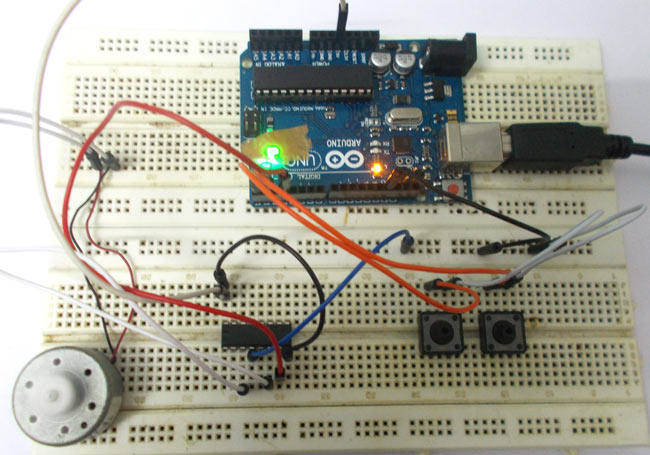
This feature is enabled in UNO to get variable voltage over constant voltage. The method of PWM is explained here; consider a simple circuit as shown in figure.
If the button is pressed if the figure, then the motor will start rotating and it will be in motion until the button is pressed. This pressing is continuous and is represented in the first wave of figure. If, for a case, consider button is pressed for 8ms and opened for 2ms over a cycle of 10ms, during this case the motor will not experience the complete 9V battery voltage as the button is pressed only for 8ms, so the RMS terminal voltage across the motor will be around 7V. Due to this reduced RMS voltage the motor will rotate but at a reduced speed. Now the average turn on over a period of 10ms = Turn ON time/ (Turn ON time + Turn OFF time), this is called duty cycle and is of 80% (8/ (8+2)).
In second and third cases the button is pressed even lesser time compared to first case. Because of this, the RMS terminal voltage at the motor terminals gets even decreased further. Due to this reduced voltage the motor speed even decreases further. This decrease in speed with duty cycle continuous to happen until a point, where the motor terminal voltage will not be sufficient to turn the motor.
So by this we can conclude the PWM can be used to vary the motor speed.
Before going further we need to discuss the H-BRIDGE. Now this circuit has mainly two functions, first is to drive a DC motor from low power control signals and the other is to change the direction of rotation of DC motor.
Figure 1
Figure 2
We all know that for a DC motor, to change the direction of rotation, we need to change the polarities of supply voltage of motor. So to change the polarities we use H-bridge. Now in above figure1 we have fours switches. As shown in figure2, for the motor to rotate A1 and A2 are closed. Because of this, current flows through the motor from right to left, as shown in 2nd part of figure3. For now consider the motor rotates clockwise direction. Now if the switches A1 and A2 are opened, B1 and B2 are closed. The current through the motor flows from left to right as shown in 1st part of figure3. This direction of current flow is opposite to the first one and so we see an opposite potential at motor terminal to the first one, so the motor rotates anti clock wise. This is how an H-BRIDGE works. However low power motors can be driven by a H-BRIDGE IC L293D.
L293D is an H-BRIDGE IC designed for driving low power DC motors and is shown in figure. This IC consists two h-bridges and so it can drive two DC motors. So this IC can be used to drive robot’s motors from the signals of microcontroller.
Read More: DC Motor Control using Arduino