Update 11/22/2013: Thanks to everyone who voted for this project in theMicrocontroller Contest! It was one of three first-prize winners.
Update 9/17/2013: Thanks to everyone who voted for this project in the Arduino contest (I was one of ten “second prize” winners)! If you want to try this project with an addressable LED strip instead of an analog strip, check out the Rainbow Jarproject (also an Arduino contest winner).
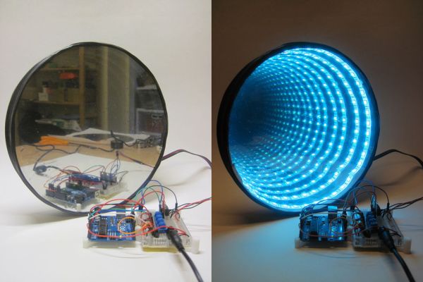
This is my take on a combination of two classic projects: RGB LED control with an Arduino, and an Infinity Mirror. It’s an RGB LED infinity mirror that lets you toggle between an adjustable-speed color-fade mode and a direct-control mode where you individually set the red, green, and blue LED brightness levels. The primary inspiration for this particular project comes from this infinity mirror Instructable andAdafruit’s RGB LED Strip tutorial, but there are many more quality resources out there on both projects.
I’ve done my best to gear this project towards newbies by providing an exact list of materials I used and the exact procedure that I followed. One recurring theme I’ve noticed in comment sections for other infinity mirrors is a lack of links to specific parts (e.g. exactly what type of LEDs or LED strips were used, what power supply, where to buy the mirrors, the enclosure…). Clearly, if you know what you’re doing and want to spend more (or less) money to design a slightly different mirror, you can adjust your materials as needed, use a different Arduino board, etc. You can skip the Arduino entirely and make a pretty simple, cheap infinity mirror if you want (just search Instructables for “infinity mirror” and you’ll find a few), or go crazy and spend hundreds if not thousands of dollars (search YouTube for “infinity mirror table” and you’ll get the idea).
So, on to the materials list. Remember that this is an exact list of parts that I used, but I gradually cobbled together the supplies for this project over a long period of time. I didn’t sit down, compare vendors (e.g. Adafruit vs. Sparkfun) and find the absolute cheapest way to build this. So, feel free to shop around to bring down the cost (and post links in the comments if you find a better/cheaper version of a certain part!). Quantities are just 1 (one) unless otherwise noted, prices are rounded to the nearest dollar as of September 2013.
Materials: Electronics
- Arduino UNO R3 with mini breadboard and jumper wires. I have the Getting Started with Arduino Kit from Maker Shed ($65).
- (Optional): Arduino/breadboard holder. The Maker Shed kit didn’t come with one – I 3D printed this cool minimalist design I found on Thingiverse.
- 1 meter RGB LED strip ($25). This is an analog strip, which means you can only control the color of the whole strip at once. SparkFun also carries a digital RGB LED strip which has individually addressable LEDs (if you wanted to send pulses of light down the strip one LED at a time, or have some other pattern), but it’s more expensive ($45) and you’ll need completely different Arduino code. Both strips can be cut to length to fit your mirror.
- Four 10K potentiometers ($1 each).
- Three N-channel MOSFETs ($1 each).
- SPDT power switch ($1.50).
- 22 AWG hookup wire (black), 100 feet ($8). This is only required if you pref to color-code your V+ and ground connections with red and black respectively. Otherwise you can just use the multi-colored jumper wires that come with most Arduino kits. 100 feet is also WAY more than you’ll need for this project, but you can never have too much hookup wire! You can get a smaller 25′ roll from SparkFun.
- 22 AWG hookup wire (red), 100 feet ($8). Same note as above, with smaller roll here.
- Barrel jack breadboard adapter ($1).
- 12V/5A DC power supply ($25). This is a big place to potentially save money. The RGB LED strip I used requires 12V, and according to the datasheet, draws 60mA for every 3-LED segment (the smallest unit the strip can be cut into). So at 60 LEDs for the whole strip, that’s an absolute maximum of 1.2A at full brightness. I had a 12V charger laying around from some old long-forgotten device, but it was only rated at 0.5A and couldn’t light the whole strip. So, I went ahead and bought a beefy supply because I figured it would be useful for future projects anyway. Adafruit and SparkFun both carry smaller, cheaper 12V supplies (1A and 600mA respectively) that might suit your needs just fine depending on the size of your mirror and how many LEDs it will use. You could also scavenge something like an old laptop charger, but be sure to check the output voltage and current specs (usually printed on the label).
Materials: Building the Mirror
[box color=”#985D00″ bg=”#FFF8CB” font=”verdana” fontsize=”14 ” radius=”20 ” border=”#985D12″ float=”right” head=”Major Components in Project” headbg=”#FFEB70″ headcolor=”#985D00″]
Important: there are three main parts that need to fit together to build this: the regular mirror, the frame, and the one-way mirror. First, it’s easiest if you can find a cardboard/paper mache lid and a regular mirror that will fit snugly inside it – the parts I bought didn’t fit together perfectly, so I had to use a workaround (see Step 6). Second, cutting acrylic can be a pain depending on the tools you have available, so plan accordingly (see Steps 9 and 10). There’s also an important consideration regarding the LED strip, which can’t be cut to any length – it has to be cut in multiples of 3-LED segments, which are just shy of 2″ long – so you want the inside perimeter of your mirror frame to be a multiple of that length. So, I’ll link to the parts I used to build my mirror, but you can still follow these directions to build a mirror of a different size or shape.
- 9″ diameter circular mirror. I bought this kit of 7 mirrors ($14) with the intent of also making some smaller infinity mirrors.
- Kit of 8″, 9″, and 10″ diameter round paper mache boxes ($9). Important – I bought these hoping that the 9″ diameter mirror would fit snugly inside either the 9″ lid or the box itself (and because I couldn’t find individual boxes for sale on Amazon). It didn’t. The 9″ lid was just too small, and the 10″ box was too big. So, I made it work by cutting out the top of the 9″ lid, and just using the rim. This will make sense if you skip ahead and look at the pictures in Step 6. Point being,ideally you should use a mirror that fits snugly inside a paper mache lid or box.
- 1/8″ thick 12″x12″ sheet of clear cast acrylic (plexiglass). Available on Amazon($8) and McMaster-Carr ($9). Acrylic is super easy to cut if you have access to a laser cutter. I don’t, so I tried using a jigsaw (Step 9) and a score-and-snap method (Step 10). Both worked reasonably well but resulted in some jagged edges, and in hindsight would have worked much better for a rectangular mirror instead of a round one. If you want to build a slightly smaller mirror, McMaster sells pre-cut 6″ diameter circles. I didn’t shop around much for larger pre-cut circles but you might be able to find them.
- Mirrored window tint. I ordered this stuff from Amazon ($27) but you can easily find this in hardware stores. Probably hard to find in small quantities, so plan on having plenty left over.
- Black paint. I picked up a can of generic black spray paint ($3) at A.C. Moore.
- Optional: if you want to get really fancy, you might be able to order a custom-sized one way mirror, instead of putting mirrored window tint onto a piece of plexiglass. This will probably give you a higher optical quality in your final product, but I didn’t look into it.[/box]
Tools
- Soldering iron. I have this variable temperature one from SparkFun ($45). Youmight be able to get away without one, depending on how your LED strip arrives. The SparkFun product page says “You will need to solder on your own wires.”, but my strip arrived with all four wires already soldered on. Even so, pushing the ends of the (stranded) wires into a breadboard can be a pain, so I recommend soldering on small segments of solid-core wire to make that easier.
- Lead-free solder ($8).
- Wire strippers ($5), if you don’t already have a pair that can strip 22 AWG. Again, you can squeeze by without these if necessary, but I’m betting most people reading this have wire strippers.
- Mini needle nose pliers ($2) if, like me, you’re clumsy and hate handling tiny breadboard components with your fingers.
- Power drill (see Step 6 – you can probably just get away with a sharp knife)
- Super glue
- Electrical tape
Got all that? Time to start building!
Step 1: How does an infinity mirror work?
Ok, almost time to start building. First, I want to pre-emptively address another common comment: how do these things actually work?
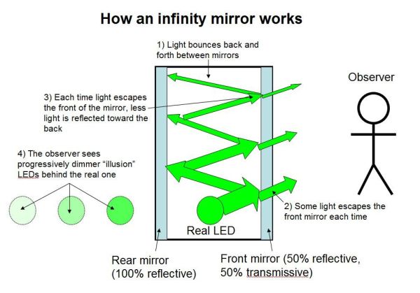
Not surprisingly, there is no magic involved. The secret is that the infinity mirror actually contains two mirrors with different transmissivity and reflectivity. For all practical intents and purposes, mirrors that we deal with in everyday life are 100% reflective (technically a tiny amount of light will also be absorbed, but we can ignore that for now). That’s the regular mirror at the “back” of the infinity mirror (on the left in the diagram above). The tinted window film, however (on the right in the diagram above), only reflects about half of the light that hits it*. This means that, when you sandwich an LED between the two mirrors, some of the light escapes through the front mirror and into your eye. The rest is bounced back off the rear mirror, then into the front mirror again, and this process continues off to infinity – thus the name. But, since a little bit of light escapes each time, each successive illusionary LED that you see will look a little bit dimmer, until they gradually disappear – you can’t actually see infinitely many LEDs.
Note that this does not work because the window tint “only lets light through in one direction”, which is a common misconception. In order for the illusion to work properly, the side of the front mirror the observer is on (the outside world) must be much darker than the side with the LEDs (inside the infinity mirror). This is the same effect that you see in crime dramas/movies where someone is held in an interrogation room that has a mirror on the wall, but there are people on the other side of that mirror observing as though it’s just a window. That only works if the interrogation room is well-lit and the observation room is dark.
*The exact percentages of reflectivity/transmissivity might vary depending on what kind you buy – different levels of reflectivity and transmissivity are actually regulated in different states for use in car windows, Google it if you’re curious.
Step 2: Building the Circuit
It’s probably a good idea to build, test, and debug your circuit before you build the mirror. Otherwise, it would be quite sad if you get a nice, fancy mirror built only to throw the switch and find out something doesn’t work. So, first let’s assemble the circuit and test the LED strip. If you’re new to circuits and don’t understand what’s going on, you can either (a) just blindly follow the directions, or (b) look ahead to the next step for an explanation of how the circuit works.
If you have experience working with breadboards, you can go ahead and assemble the circuit based on the third breadboard diagram above, or directly from the circuit diagram. For newbies I broke it into three steps, hopefully to make things less overwhelming – corresponding to the first three diagrams above:
1) Populate the breadboard with the three MOSFETs, four potentiometers, SPDT switch, and barrel jack adapter. I made these parts “transparent” in the figure above so you can see exactly where their pins go*.
2) Add wires to connect to your power and ground rails. I’ve color-coded these with red and black here, but remember that you can use whatever colors you want if you just have a multi-colored jumper wire kit and no red and black hookup wire. Notice how one of the breadboard rails is connected to the +12V supply from the barrel jack (which feeds power to the Arduino through Vin), and one is connected to the Arduino’s +5V power pin, but they share a common ground. Whatever else you do, don’t short the +12V and +5V supplies together!
3) Add wires to connect to the Arduino’s inputs and outputs, and wires that you will connect to your LED strip (if your strip came with pre-soldered wires, use those)**. Again, I’ve color-coded the respective red, green, and blue wires here but your ability to do that will depend on what wire you have available.
* I started making this diagram in Fritzing, but got frustrated with the enormous amount of space components like MOSFETs and potentiometers take up in breadboard view mode (they give a quasi-3D view instead of a “top-down” view, so take up way more space than they do in real life and obscure other things on the breadboard). So, I took a screenshot of the Arduino and breadboard and drew over them in Powerpoint.
** If your LED strip did come with pre-soldered wires, be careful about the color coding. SparkFun’s product page notes that the blue and green wires are switched, which can be irritating but won’t cause any harm. My strip came with a black wire connected to V+, and getting the polarity reversed on the LED strip could be bad news. I guess I understand not wanting to use two red wires (one for V+ and one for the red LEDs) but I wish they’d use something other than black for V+.
Step 3: How Does the Circuit Work?
This is a rough explanation of how the circuit works and what the components are for. Seasoned veterans can skip this step, but read on if you’re curious. I don’t have time to write a whole introductory chapter on circuits so I’ve tried to provide relevant links when possible.
- The barrel jack adapter provides a +12V supply to the breadboard. This is required to power the LED strips, and also powers the Arduino through its Vin pin. Technically, the Arduino’s built-in barrel plug will accept a +12V supply, which you can then access through the Vin pin, but the LEDs draw a lot of current – more than you want running through the Arduino board. This way, the current “splits up” – the Arduino only draws what it needs, and the high current goes straight to the LEDs through the breadboard. Special thanks to theAdafruit support forums for helping me figure this out.
- The SPDT switch just acts as a toggle to select which “mode” the program is in. The details of the code are explained in the next step, but essentially it just switches between a “color fade” mode that rotates through different colors, and a direct-control mode where you control individual red, green, and blue LED brightness. The middle pin of the switch is connected to one of the Arduino’s digital input pins, and the outer two pins are connected to +5V and ground. So, depending on which way the switch is flipped, the program reads a digital HIGH or LOW using the digitalRead() function and acts accordingly (note: SPDT stands for “single-pole double-throw”, the Wikipedia page on switches has a nice table summarizing the different types of switches, with diagrams).
- The potentiometers are your “controls” depending on which mode the program is in. In individual-control mode, the three potentiometers control brightness of the red, green, and blue LEDs respectively. In color-fade mode, a single potentiometer controls the speed of the fading. The potentiometers have three pins. Like the switch, one pin is connected to +5V, and one pin to ground. However, unlike the switch, rotating the potentiometer makes the voltage on the middle pin vary continuously between 0V and 5V, instead of just toggling between the two. So, the middle pins of the potentiometers are connected to the Arduino’s analog inputs. Then, using the analogRead() function, the Arduino converts that voltage to a number between 0 and 1023 for use in the program (see next step).
- The MOSFETs are probably the trickiest part to understand for a newcomer to electronics. These are required to drive “high power” devices like motors, solenoids and LED strips, which frequently require more current than the Arduino can supply. The Wikipedia page on these is actually rather dense, so I’ll try to give a simplified explanation here. The MOSFET has three pins, called the “gate” (G), “drain” (D), and “source” (S). In its simplest form, the MOSFET acts like a valve that lets current flow from the drain to the source. The “gate” controls this valve (think of opening and closing a valve to a garden hose), except that control is electrical instead of mechanical. A voltage applied to the gate from one of the Arduino’s output pins turns the MOSFET “on” – allowing high current to flow from the drain to the source, without actually drawing any current from the Arduino. If the voltage to the gate from the Arduino is zero, the MOSFET shuts off and stops current from flowing. This way you can control even enormous motors and lights with a tiny little Arduino, as long as you have an external power supply big enough to handle it.
- I should also mention pulse width modulation (PWM). This is a common technique used to control LED brightness with an Arduino. In short, the Arduino’s output pins are digital, so they can only output a HIGH or a LOW (5V or 0V). They can’t continuously vary their voltage to adjust something like LED brightness or motor speed. Instead, what they can do is send out very rapid pulses (roughly 500 times per second with the Arduino), much faster than the human eye can see. Each pulse consists of a HIGH segment and a LOW segment, and the relative ratio between the two determines the “brightness” that we actually see. A pulse that is 0% high and 100% low will just look like “off”. 100% high and 0% low will be “full brightness”, and 50% high/50% low will be about half-brightness. You get the idea. In this circuit, a PWM signal is sent to the MOSFETs, which then controls the high current going through the LEDs, allowing a “fading” effect and adjustable brightness.
Step 4: Arduino Code
Copy and paste the Arduino code below into a new sketch. I won’t write my own tutorial here, so if you don’t know how to create/upload a sketch, check out the official Arduino – Getting Started page. If you want to learn more about a specific command, just Google it (e.g. “Arduino analogWrite”) and the official help page should pop right up.
Caveat: this probably isn’t the most efficient code! Particularly, I’m not sure of a nicer way to continuously monitor the fade-speed potentiometer without copying and pasting the same line of code over and over, or if there’s a way to break out of a for loop if you flip the toggle switch (right now, if you switch to individual-control mode while in color-fade mode, the switch won’t occur until it finishes the current fade cycle). So, I’ll throw that out there as a challenge to anyone who’s reading this and wants to post better code. Clearly I’m a mechanical engineer at heart and not a programmer.
// Arduino code to control and RGB LED strip
// Uses a toggle switch to switch between color-fade mode
// and individual RGB control mode
// adapted from http://learn.adafruit.com/rgb-led-strips/example-codeconst int RED = 9; // define digital output pins for individual red,
const int GREEN = 10; //green and blue channels
const int BLUE = 11;const int POT1 = 0; // define analog input pins for three potentiometers
const int POT2 = 1;
const int POT3 = 2;
const int POT4 = 3;const int BUTTON = 2; // define digital input pin for the switch
int val = 0; // stores the state of the switch input pin
int FADESPEED = 0; // initiate fade speed set by potentiometer
int r = 0; // initialize the red, green and blue values
int g = 0;
int b = 0;
void setup(){
pinMode(RED, OUTPUT); // define digital pins as outputs and inputs as needed
pinMode(GREEN, OUTPUT);
pinMode(BLUE, OUTPUT);
pinMode(BUTTON, INPUT);
}void loop(){
val = digitalRead(BUTTON); // read the input value from the toggle switchif (val == HIGH){
// code for RGB color fade
FADESPEED = analogRead(POT4)/10; // set the fade speed by reading analog input from 4th potentiometer
// analogRead will output a number between 0 and 1023, and “delay”
// is in milliseconds, so the biggest delay you’ll get here is about
// 1/10 of a second. Divide by a different number to change the max
// fade time.
// fade from blue to violet
for (r = 0; r < 256; r++) {
analogWrite(RED, r);
FADESPEED = analogRead(POT4)/10; // check the fade speed continuously, otherwise
// it won’t update until it’s gone through a complete cycle.
// Probably not the most efficient way to do this…
delay(FADESPEED);
}
// fade from violet to red
for (b = 255; b > 0; b–) {
analogWrite(BLUE, b);
FADESPEED = analogRead(POT4)/10;
delay(FADESPEED);
}
// fade from red to yellow
for (g = 0; g < 256; g++) {
analogWrite(GREEN, g);
FADESPEED = analogRead(POT4)/10;
delay(FADESPEED);
}
// fade from yellow to green
for (r = 255; r > 0; r–) {
analogWrite(RED, r);
FADESPEED = analogRead(POT4)/10;
delay(FADESPEED);
}
// fade from green to teal
for (b = 0; b < 256; b++) {
analogWrite(BLUE, b);
FADESPEED = analogRead(POT4)/10;
delay(FADESPEED);
}
// fade from teal to blue
for (g = 255; g > 0; g–) {
analogWrite(GREEN, g);
FADESPEED = analogRead(POT4)/10;
delay(FADESPEED);
}
}
else {
// code for individual RGB control with potentiometers
r = analogRead(POT3)/4; // read values from the 3 potentiometers and divide by 4 to set brightness
g = analogRead(POT2)/4; // note that analog read is 10-bit (0-1023), analog write is an 8-bit PWM
b = analogRead(POT1)/4; // signal so you need to divide this value by 4.analogWrite(RED, r); // write analog values to red, green and blue output pins
analogWrite(GREEN, g);
analogWrite(BLUE, b);
}}
For more detail: Arduino-controlled RGB LED Infinity Mirror