This project is part of the Arduino Jam 2012.
First of all we would like to thank the organization and especially the main sponsor, Capgemini, which made all of this possible.
At the Arduino Jam, during the brainstormsession, we came with the idea to make a classic Buzzwire game, but with some extra features to make it fun and off course to have a good reason for using a Arduino.
I teamed up with Jan Verstreken and continued for a while with brainstorming about possibilities for the “features”. We came up with a very good idea, in fact it was such an amazingly cool, futuristic hypermultifunctional environmental changing idea, that we’ve tought the world might not be ready for something like that yet, so we just discarded it and came up with this:
An Xtremely tuned version of the classic buzzwire game :-). It’s made for 2 players with checkpoints and… a ring that shrinks between 2 checkpoints.
Also, if you “Buzz the wire”, the other person’s ring grows and you will have to go back to the previous checkpoint before you can continue to the next one, where your ring will grow back to the initial diameter.
And off course it has some visual feedback with LED’s and a speaker to indicate a “Buzz” and giving start- and victory tunes.
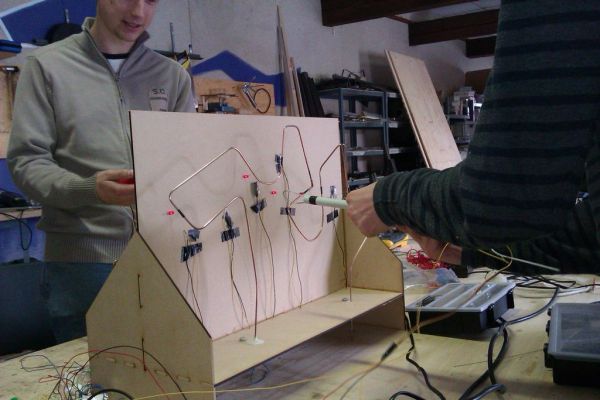
The finished Xtreme BuzzWire-4-2 in action!:
All this, from idea to full working, playable prototype, was done in less than 48 hours during the very first Arduino jam at the Timelab in Ghent, Belgium.
All credits for the construction and craftwork goes to my companion Jan who created the whole thing. I just helped to hold stuff in place, collecting materials, giving ideas and things like that 🙂
Most of the programming was done by me, but after writing the basic setup and functions we both worked on it to remove the little bugs and finetune everything.
At the end of the Jam our project got the most votes from the other jammers and visitors! But it’s surely worth it to take a look at the other jammers’ projects too! (found on the link on top of this intro). They were all pretty awesome projects, made by pretty awesome and clever people.
Before we start with the instruction steps, I want to thank all the people who made this awesome event possible, especially Instructable-member cinezaster who did most of the organisation, and Timelab, and off course the main sponser Capgemini.
And also thanks to all the other jammers and my companion Jan for making this weekend an succesfull and awesome first belgian Arduino Jam (of many more to follow I hope).
Enough blabla, let’s go to the instructions 😉
Step 1: Materials & used tools
TOOLS:
– ARDUINO. We used a UNO, but any will do, I guess.
– Breadboard and jumpwires
– a computer with arduino software installed.
– Soldering equipment
– wirestripper/cutter, screwdriver, you know… basic tools
– Something to drill small holes like a dremel or something.
– something to cut out your platform (we used a lasercutter, but jou can just be creative)
-something to put stuff together. …We found out that 2-component-harsh is a SUPER-efficiënt magic material 🙂 But hot glue might do the trick too.
MATERIALS & other Equipment:
=steel cable (like for bicycle brakes) for the growing/shrinking ring and checkpoints
– Something long and conductive that you can bend for the BuzzWire. We used 4 Cu-rods soldered together as 2 long rods.
– wood or anything you can make a platform with. (we use MDF)
– !0 LED’s and resistors (220 – 330 ohms) for checkpoint indicators
– 8 resistors (220 ohms) for voltage devider (see next step)
= 2resistors 10k
– 10K potentiometer… any type will do.
– some different colored hookup wire
– isolating tape or duct tape (off course!) 😉
– 2 hobby/RC servo motors
– nuts and bolts for the start and finish contacts
– Something to make 2 handles that also will support the servo’s (we used a paintrollers handle with a piece of PVC-tube)
– Lots of caffeïne 😉
Step 2: The schematic
This is the complete schematic for the BuzzWire-4-2. (And YES, I know this drawing looks crappy 😉 )
I suggest to use 2 standard breadboards, or if you like, you can use some proto PCB board and put everything together in 1 place. Or maybe you can make a Arduino BuzzWire-shield… I’dd like that 🙂
For now we can ignore the servo’s and Player1/Player2 pins (analogPin 0&1 respectively). You can connect these when the handles are build.
The signal pin from player1’s servo on the handle will go to digital pin9, and player2’s to pin 10
On one breadboard, set-up the 2 74HC595 shift-registers, and the resistors to the LED’s… You can also put the LED’s lower on the breadboard for testing before you put them on the platform if you want.
On each shift-register outputs Q0 – Q4 are used, representing checkpoints 1-5 for both players (IC connected straight to arduino is player1)
Data-pin is connected to I/O pin11 on arduino.
Clock-pin is connected to I/O pin12 on arduino.
Latch-pin is connected to I/O pin8 on arduino.
Lots of useful information including how to connect the 74HC595’s can be found athttp://www.arduino.cc/en/Tutorial/ShiftOut
Connect one end of the speaker to I/0 pin2 on the arduino and the other end to the ground. Not much to explain here.
On the second breadboard, set up a voltage divider with 8 resistors of 220ohms, one end to ground, other to 5V from arduino.
This will be used to make the 5 checkpoints, start, finish, and wire-touched detection on 1 single arduino pin per player.
The +5V-side will later on be connected to the BuzzWire, after the first resistor starting from there to the Finish-contact, next to the contacts for checkpoint5, then 4 and so on down to to 1,
Before the last one is the start-contact. (don’t worry, how we made the start-finish and checkpoints contacts comes in the building steps!)
Later on, when we made the “variable ring” with the steel cable, we’ll connect that to analog pins 0 and 1. And trough a 10k resistor to the ground.
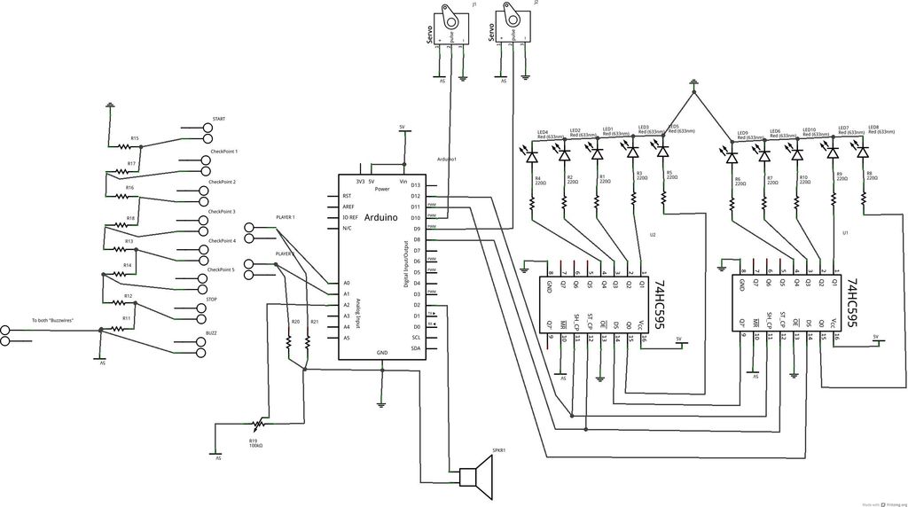
Last plug a potentiometer (10K or something) in your breadboard between +5V en GND, and hook the sensorpin to arduino’s analog Pin2. This will be used to adjust the difficulty (speed) of the game.
Now let’s go take a short look at the code,
– Breadboard and jumpwires
– a computer with arduino software installed.
– Soldering equipment
– wirestripper/cutter, screwdriver, you know… basic tools
– Something to drill small holes like a dremel or something.
– something to cut out your platform (we used a lasercutter, but jou can just be creative)
-something to put stuff together. …We found out that 2-component-harsh is a SUPER-efficiënt magic material 🙂 But hot glue might do the trick too.
For more detail: Xtreme Buzzwire-4-2 Arduino Jam project