
Wizard Chess is a form of chess originally invented by J.K. Rowling in Harry Potter and the Sorcerer’s Stone. The characters give verbal commands to the chess pieces and they move by magic. Seems impossible right? Not anymore! Using an Arduino Uno, along with an XY plotter, Wizard Chess can be recreated in real life! You can now play a full game of chess using voice commands and the chess pieces will automatically react accordingly.
Created by Divyank Shah in association with Berbawy Makers. Divyank Shah is an ambitious high schooler looking to study further in computer science with a deep interest in microcontroller and microprocessing technologies
A special thanks to Ms. Berbawy and her Principles of Engineering class that made this project possible!
Supplies
● 3 x 20 Tooth 5mm Bore Pulley
● 4 x 8mm by 24mm Linear Bearing
● 12V 3A Power Supply (Minimum)
● 32 x 6mm by 2mm Neodymium Disc Magnets
● 3D Printer (Ender 3 V2 & Prusa Mini Used)
● Caliper
● Wood Glue
● Laser Cutter
● CAD Software (OnShape Used)
● Adobe Illustrator
● 2 x 12″ by 24″ by 1/4″ Plywood
● 2x 12″ by 24″ by 1/4″ Plywood
● Wood Glue
● Sandpaper/Filer
Step 1: Electronics Assembly
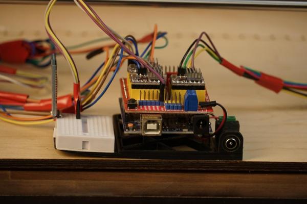
After gathering all the materials and tools, start by fixing the CNC shield upon the Arduino. Insert the 3 DRV8825 stepper drivers into the X, Y, and Z labeled sections (Section A remains empty). Be sure to add the heatsinks to the stepper drivers prior to attaching to the CNC shield. Ensure the enable pin on the stepper driver aligns with the enable pin on the CNC shield.
Once all stepper drivers are connected, connect the power supply terminals to the power terminal blocks on the CNC shield and set the VREF values appropriately. The formula to solve for VREF on a DRV8825 is voltage_read * 2 = current_limit. This formula is different for various drivers, please check your driver’s specifications before continuing as too much current will melt the coils and insufficient current will prevent the motor from moving. The current_limit is determined by the stepper motor specifications. Refer to the data sheets for your motors to ensure you do not over-power or under-power the stepper motors. Once the drivers are connected and set, connect the stepper motor cables to the 4 pins allocated. Once again, refer to the data sheet as many manufacturers may have changed the wiring for your stepper motors. Run a sample test program to determine if the stepper motors are connected properly and functioning.
Optional: Install jumper caps to enable micro stepping. (Must increase number of steps in code sample if FULL step is not desired).
Connect the following devices using the wiring below:
Stepper Motors: 4 wires from the stepper driver to the 4 pins located by the stepper driver. Repeat for X Y Z sections.
HC-05: RX -> TX, TX -> RX, VCC -> 5V, GND -> GND
Electromagnet: SIG -> SpnEn, VCC -> 5V, GND -> GND
Use the provided code below to test if all 3 stepper motors are working properly.
//Used to send the number of steps
#define motorXStep 2
#define motorYStep 3
#define motorZStep 4

//Used to determine the directions of the motors (clockwise or counterclockwise)
#define motorXDir 5
#define motorYDir 6
#define motorZDir 7

//Turned to HIGH by default. Recommend attaching a 2 pin jumper cap between EN and GND on the CNC Shield.
#define enableMotors 8

//motorStep = Step Pin on Driver
//steps = Amount of Steps to Travel (200 Steps = 1 Rotation given 1.8 Degree Step Angle and Full Steps Enabled)
//delayTime = Speed of motor (Increase to move motor slower or decrease to move motor faster)

void step(int motorStep, int steps, int delayTime){
	for(int i = 0; i < steps; i++){
		digitalWrite(motorStep, HIGH);
		delay(delayTime);
		digitalWrite(motorStep, LOW);
		delay(delayTime);
	}
}

void setup(){
	pinMode(motorXStep, OUTPUT);
	pinMode(motorYStep, OUTPUT);
	pinMode(motorZStep, OUTPUT);

	pinMode(motorXDir, OUTPUT);
	pinMode(motorYDir, OUTPUT);
	pinMode(motorZDir, OUTPUT);

	//Enables the motors
	digitalWrite(8, LOW);
}

void loop(){
	//Moves the motors in a CLOCKWISE direction
	digitalWrite(motorXDir, HIGH);
	digitalWrite(motorYDir, HIGH);
	digitalWrite(motorZDir, HIGH);

	step(motorXStep, 200, 1000);
	step(motorYStep, 200, 1000);
	step(motorZStep, 200, 1000);

	digitalWrite(motorXDir, LOW);
	digitalWrite(motorYDir, LOW);
	digitalWrite(motorZDir, LOW);

	step(motorXStep, 200, 1000);
	step(motorYStep, 200, 1000);
	step(motorZStep, 200, 1000);
}
Step 2: Mechanism Assembly
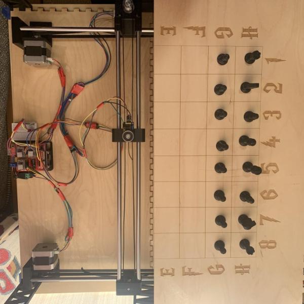
To create the linear XY plotter, understanding the overall design and structure will assist in creating a reliable system. Certain designs provide certain advantages and have different requirements and difficulty levels. The system created requires a total of 3 motors: 2 for the X axis and 1 for the Y axis. Create the stepper motor mounting bodies with holes for screws to pass through to fasten motors perpendicular to the ground. Refer to the data sheets for your stepper motor to find the appropriate dimensions.
When creating the Y Axis that will be sliding along the X Axis ensure to have a slot to loop the belt upon itself so you can fasten the belt to the slider.
Additions for limit switches can be added, but they are not required. Ensure space for linear bearings is added to allow for easy movement across the linear rods. Depending on the tolerances of your 3D printer, your dimensions may be slightly different. You may use sandpaper or a filer to shave and clean off any rough edges and excess material.
Once all the pieces have been created and printed, ensure that the linear bearings fit in their appropriate places, along with the linear rods and stepper motors. Using the various spacers and pulleys, you can set the pulleys to be center to allow for free stable movement.
When connecting the timing belt to the stepper motors, ensure that the belt is not too tight or too loose since this will later cause problems. One way to check is to move the system up and down the length of its belt. If you notice the belt is skipping over the stepper mounted pulley, it is too loose. If the belt is moving but requires a significant amount of force, then it is too tight.
Once completed ensure the direction of your stepper motors is correct. Depending on the placement of your stepper motors, you may have to reverse one of the stepper motors on the X Axis either through code or by simply switching the wiring around.
When creating the moving plotter, ensure to have the proper designs to accommodate the electromagnet.
Create a housing to host the Arduino Uno, HC-05, and barrel plug from the power supply. An extra breadboard can be attached to make the wiring cleaner and easier to manage. Standoffs to prop up the Arduino are also recommended to prevent contact from the pins.
Lastly, create the chess pieces. It is recommended that you reference a cross section of a chess piece and trace the image and revolve the the sketch to create a body. This process can be repeated for the King, Queen, Bishop, Rook, and Pawn. The special features on the Rook, Bishop, King, and Queen can be added afterwards to give a more realistic appearance. As per the knight, due to its unique shape, you will have to create it in a different manner. Ensure to add small holes at the bottom to house the magnets. Depending on the tolerances of your 3D printer, your dimensions will vary but should account to hold a 6 mm wide magnet. The entire diameter of the chess piece should not reach over 18 mm, however, these values may change depending on the size of your squares and the strength of the magnets. Make sure you are able to test these values and ensure they work for your configuration. When placing the magnets inside the chess pieces, ensure the polarity is consistent throughout the chess pieces (South pointing down or North pointing down) and ensure this works best with the electromagnet.
Step 3: Software: Arduino IDE
To run the assembly, we will be using the Arduino IDE, along with MIT App Inventor to allow interactions from our Android device to the Arduino.
Note: When uploading code to the Arduino, always unplug the RX/TX pins from the HC-05 module as the computer uses these ports and it will cause an error when uploading if plugged into the HC-05.
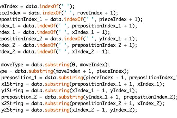
Within the Arduino IDE, we will be reading Serial input, which will come over Bluetooth, and parsing that data to help us understand what the input is asking for the chessboard to do. The input will first be split into the different words it contains, this way we can interpret each word accordingly. Since the String datatype is being used, we can use the indexOf() function to detect spaces. Using these indices, we can separate the different words using substring(). This means the chessboard will accept answers that are at least 7 words long (this can be altered to fit your style). Using the trim() function, we can get rid of any trailing whitespace. This will leave us with Strings we can interpret.
The input we receive will look something like “Move Queen from Dumbledore 4 to Dumbledore 8” or “Move Pawn to Albus 3 from Albus 2” and our current output provides us with: [“Move”, “Queen”, “from”, “Dumbledore”, “4”, “to”, “Dumbledore”, “8”].
We can now interpret the [“Dumbledore”, “4”, “Dumbledore”, “8”] and assign them numerical values that correspond with stepper motor values. We can use the toUpperCase() function to have a consistent format with our text. Since the chessboard can be seen as an XY coordinate plane with the letters as the X axis and the numbers as the Y axis, we can assign values accordingly. When assigning values, ensure that similar values are included as well, “4” might be interpreted as “FOR” or “FOUR” while “2” might be interpreted as “TWO” or “TO” or “TOO”, if you notice these cases, ensure that you add them into your code to make a easier user experience. The same concept can be applied to the words, where “Albus” may be interpreted as “Elvis.” Once again test to ensure you account for any misinterpretations within your code.
Once we have completed the XY value assignments, we can have a quick check to ensure that everything went smoothly. In the sample code provided, we have returned -1 if the value is invalid, hence we want to exit out of the function if this is the case.
We can now focus on the prepositions “to” and “from” based on their position in the input, the first square might be the destination or starting position. Hence we can create a function to create this switch if it detects that “to” comes before “from.” We can once again have a checking function to ensure that no invalid answers were given. Sample: “Move Pawn from Albus 1 to Albus 2” signifies a starting location of A1 and a destination of A2, while “Move Rook to Goblin 5 from Goblin 2” signifies a starting location of G5 and a destination of G1.
Once we have confirmed that our starting and destination squares are valid, and our prepositions are valid, we can work on validating if the piece is allowed to perform the move. Note: The Arduino will detect if the piece and move requested is allowed, however, it will not give an error if the piece were to run into another piece. We will first ensure that a valid piece is provided using the same technique used to detect if the correct XY coordinates were provided. Then, we can use a little bit of geometry to understand how pieces move. Many of the pieces move in a straight lines (Rook, Pawn, Queen & King (only in some cases)), while others move in a strictly linear fashion (Bishop (Slope of 1 & -1), Knight (Slope of 2 or 1/2), Queen (Slope of 1 & -1)). Based off of these geometric relationships, we can convert their slopes to movement using the stepper motors.
We can create various functions that help us move stepper motors in different manners. To move stepper motors together, we can use a step program that moves 1 step at the X motor, then proceeds to move the Y and/or Z motors. This will ensure that the motors move in sync.
Once we have appropriate functions, we can add functions to turn on the electromagnet ON using digitalWrite() and assigning a value of HIGH, and LOW to turn it OFF. We can call this function once we are at our starting position and turn off the electromagnet once we have reached the destination square.
Finally, within void setup(), we can establish our output pins using pinMode() according to the Arduino CNC Shield pinout. Reminder to assign pin 8 a value of LOW to enable the stepper motors (HIGH by default). You can also attach a jumper cap on the enable pins as an alternative. We also need to establish our baud rate for the Serial monitor using Serial.begin(), a value of 9600 is acceptable, however, a higher baud rate is recommended. Within void loop(), we can establish the Serial communication and ensure we are able to receive information through Serial communication.
Step 4: Software: MIT App Inventor

Ensure you have an account associated with Google to be able to login to MIT App Inventor. Starting a new project will lead us to a blank user interface. We will first add the necessary components to the UI and then create the logic using the provided block programming. The user interface can be customized to your liking but ensure to have a List Picker and at least 1 Button that will serve as the voice input button.
Ensure to include the following nonvisible components: Speech Recognizer, Bluetooth Client, and a Clock. These are the required components, however, more may be added.
Once you have completed the UI, we can begin to code the logic using the Blocks tab. We can setup the code to have the List Picker show the Addresses and Names of the Bluetooth Client. We can also add a verification label that displays “Connected” when a bluetooth connection is established or “Disconnected” otherwise. Lastly, we need to setup a button to send text over bluetooth using the speech recognizer.
Source: Wizard Chess