
Summary of Using A Bar Graph With The Arduino
This article demonstrates building a bar graph using an Arduino to visualize data or potentiometer positions. It covers wiring 10 LEDs with resistors, either as discrete components or a pre-made segment bar graph. The guide includes code to test the circuit with various lighting patterns like scanning up/down or sequential blinking. Finally, it explains integrating a trimmer potentiometer and piezo buzzer to create an interactive indicator system controlled by user input.
Parts used in Bar Graph with Arduino:
- 10 x LEDs
- 1 x 10 Segment Bar Graph
- 10 x 330 Ohm Resistors
- 10K Trimmer Potentiometer
- 1 x Piezo Buzzer
Introduction
This project explores a couple of ways of simulating and using a bar graph with the Arduino. Bar graph components like the following one can be used,
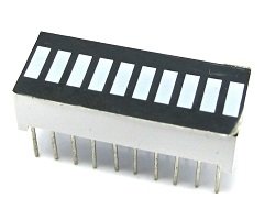
This type of bar graph is basically just 10 LEDs in a row with anodes on one side of the component and cathodes on the other.
The same thing can be created by just placing 10 LEDs on a breadboard. If you have LEDs smaller than 5mm, you may be able to get them closer together on the breadboard. If not, just space out as you see in the diagrams.
You Will Need
- 10 x LEDs or 1 x 10 Segement Bar Graph
- 10 x 330 Ohm Resistors
- 10K Trimmer Potentiometer
- 1 x Piezo Buzzer
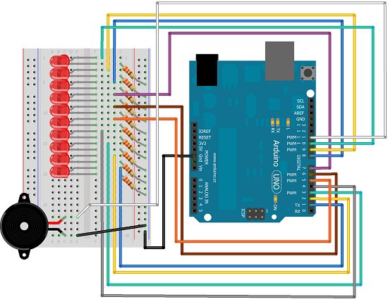
Making The Circuit – Bar Graph
The first job is to connect up all of those LEDs and resistors to make the bar graph.
Programming The Arduino – Bar Graph
Here is some code to test that the bar graph has been wired correctly.
int ledPin[] = {1,2,3,4,5,6,7,8,9,10};

void setup()

{

for (int i =0;i<10;i++)

{

pinMode(ledPin[i], OUTPUT);

}

}
void loop()
{
upanddown();
delay(1000);
oneatatime();
delay(1000);
}
void alloff()
{
for (int i =0;i<10;i++)
{
digitalWrite(ledPin[i], LOW);
}
}
void allon()
{
for (int i =0;i<10;i++)
{
digitalWrite(ledPin[i], HIGH);
}
}
void showUpTo(byte numtoshow)
{
alloff();
for (byte i = 0;i<numtoshow;i++)
{
digitalWrite(ledPin[i],HIGH);
}
}
void upanddown()
{
for (int i =0;i<10;i++)
{
digitalWrite(ledPin[i], HIGH);
delay(100);
}
for (int i=9;i>=0;i–)
{
digitalWrite(ledPin[i], LOW);
delay(100);
}
}
void oneatatime()
{
for (int i =0;i<10;i++)
{
digitalWrite(ledPin[i], HIGH);
delay(100);
digitalWrite(ledPin[i], LOW);
delay(100);
}
}
Making The Circuit – Trimpot
Adding a trimpot to control the bar graph allows the bar graph to be used as an indicator for the position of the potentiometer.
For more detail: Using A Bar Graph With The Arduino
- How do you wire the LEDs for the bar graph?
Connect all LEDs and resistors together on a breadboard or use a single 10-segment bar graph component. - Can I use individual LEDs instead of a bar graph component?
Yes, you can place 10 separate LEDs on a breadboard if they are spaced correctly. - What resistor values are required for this project?
The project requires ten 330 Ohm resistors, one for each LED. - Does the code allow for sequential lighting patterns?
Yes, the provided code includes functions to light LEDs up and down or one at a time. - How can the bar graph be used as a position indicator?
Adding a trimpot allows the bar graph to indicate the position of the potentiometer. - What is the function of the piezo buzzer in this setup?
The piezo buzzer is included as a component needed for the project alongside the other parts. - How many pins are assigned to the LEDs in the code?
The code assigns ten pins, numbered 1 through 10, to control the LEDs. - What happens when the showUpTo function is called?
This function turns off all LEDs first and then lights up a specific number of them based on the input.
