

Presented here is an ATmega328P microcontroller-based ultra low power sensor hub using nRF24L01+ radio frequency (RF) transceiver modules having transmitter and receiver units.
The transmitter sends humidity and temperature values of a place to the receiver kept at a remote location for display on an OLED module.
The nRF24L01+ module used in the receiver unit is a 2.4GHz transceiver suitable for ultra-low-power wireless applications. It is designed for operation in ISM band (industrial, scientific and medical radio band) of 2.400-2.4835GHz.
The nRF24L01+PA and LNA module used in the transmitter unit is similar to nRF24L01+ but has built-in power amplifier (PA) and low-noise amplifier (LNA) circuits, which help transmit the signal to a longer distance and achieve more stable performance for industry-standard applications.
The search for a low-power system started when some EFY readers questioned a DIY of mine, saying that ATmega328P processor would not sustain 3.3/5 volts. But it worked well because of the extreme low power capability of the ATmega processor. More detail is provided under extreme low power sub-head of this article.
Ultra low power sensor circuit
The heart of the sensor hub is the low-power ATmega328P, which runs at internal 4MHz speed. A DHT22 sensor is used to pick up the relative humidity and temperature of the area. Low-power radio transceiver module nRF24L01+PA LNA (Fig. 1) transmitter transmits the signal.

nRF24L01+PA LNA module
You can add more sensors as lots of GPIO pins of the transceiver module are unused. A 470µF capacitor acts as the stabiliser, while the sensor (radio) module draws power on burst.
Parameters for radios in both the transmitter and receiver modules are set as follows:
Data Rate = 250kBps
RF_CH = 0x6c [108]
Model = nRF24L01+
CRC Length = 16 bits
PA Power = PA_MAX
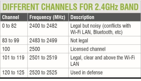
RF_CH = 0x6c is the 108th channel. Normally, the 2.4GHz band is divided into a variety of channels as shown in the table.
The 108th channel is at around 2.508GHz, which is well above Wi-Fi LAN frequency and legal to use. You can set the module to operate on 250kBps data rate and at different channels. Chances of dissemination are fairly high at 250kBps data rate. Interestingly, almost all microwave ovens operate at 2.4GHz. Therefore channels 0-82 are very noisy. The script for this project is designed such that first all the radio details are printed on the serial terminal and then the data starts appearing.
Principle of operation
The ATmega328P processor is a low-power version of ATmega328 chip. Its supply current vs frequency graph, as per the datasheet, is shown in Fig. 2. As can be seen, the processor is quite tolerant from 1.8 volts up to 5.5 volts at 1MHz, 1.8V, 25ºC.
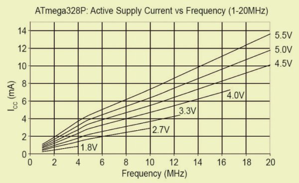
Supply current vs frequency
The processor works in active mode at 0.2µA, power-down mode at 0.1µA and power-save mode at 0.75µA (including 32kHz RTC). Getting a 0.2µA current for deep-sleep power-down mode, however, is tricky. At the same time, getting around 1µA in deep-sleep mode is easy, with the help of the chip’s watchdog timer (WDT) and brown-out detection fuse.
First, turn off the brown-out detection fuse so that low-voltage operation becomes possible without resetting. As the voltage goes down, so does the current (refer the graph in Fig. 2).
Interestingly, as the frequency goes down, so does the power consumption. That means if the chip is designed to work on a lower resonating frequency, the power consumption will further reduce. To reduce the frequency of operation, we divide the 8MHz frequency internally by commands. At 3.3V operation, power consumption goes down as follows:
[stextbox id=”info”]
clock_div_1-3.1 mA clock_div_2 – 1.8 mA
clock_div_4-1.1 mA clock_div_8 – 750 μA
clock_div_16-550 μA cock_div_32 – 393 μA
clock_div_64-351 μA clock_div_128 – 296 μA
clock_div_256 – 288 μA
[/stextbox]
To reduce the frequency of operation, here’s a very simple command to use inside setup( ):
[stextbox id=”info”]// slow clock to divide by 256
clock_prescale_set (clock_div_256);[/stextbox]
As per Fig. 2, at 4MHz, the chip will continue to work off 1.8V supply.
If the WDT is turned off, the chip will get sleep current to the tune of 1µA, but it will not wake up on its own—unless you give it a shock through interrupter (0) from pin 4 of ATmega328P, momentarily making it ground.
However, in this project we want it to send signals periodically (once every 42 minutes). Therefore we don’t set the WDT ‘off.’ The sleep current will be more than 30µA but the operation will be periodic on its own. The WDT clock is not very precise as compared to other methods of time keeping. However, at low power, the WDT clock does not differ much from real-time clocks. The entire operation is accomplished with the help of a library file called lowpower.h